Magnetically Coupled Thruster
Posted: Jun 18th, 2022, 4:42 pm
Hi,
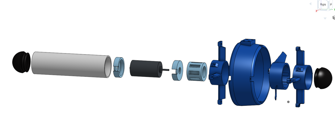
I have designed and made my own thruster for Stingray, my ROV-in-progress. It was quite a challenge since not many people seem to have used magnetic coupling successfully. It's design was partly influenced by my manager, who suggested the idea to me. I also looked at the (very few) YouTube videos of various designs, as well as Steve's designs from the Homebuiltrovs.com main website. I used a ring-shaped prop design, with 8 neodymium magnets (north-south alternating polarity) glued in with epoxy. These lock in to the 8 corresponding magnets in the rotor, inside the main housing. One of my main concerns when designing the magnetic coupling was how much force the magnets would be able to transmit before slipping, but after a bit of trial and error, It takes a surprisingly large amount of force to cause the magnets to slip!
The main housing is PVC pipe (43mm OD), and the end caps are large dome-shaped furniture feet (with O-rings sealing the water out). A cheap brushed DC motor resides inside the main housing. the ring-shaped prop simply slides over the PVC pipe and locks on to the magnets. The prop guard and spokes slide on to the main housing in a similar fashion, securing in place firmly with two grub screws (although they fit fairly tightly without the grub screws). All of the light blue (internal) parts in the CAD pictures are 3D printed in PLA, and the dark blue (external) parts are printed in PETG.
I cheated a bit for the prop design - I used the blade profile of the Blue Robotics T100 thruster. I figured it would be a good idea to use blade profiles from someone who has qualifications in fluid dynamics!
The spoke parts also act as thrust bearings, stopping the prop from shooting off! I used a thin Teflon sheet for reducing friction between the prop, thrust bearings and the PVC pipe. This worked better than expected, and is very simple and easy to make. The prop and Teflon discs can be easily removed and cleaned/replaced in just a few minutes, which should prove useful for maintenance in the field.
The thruster makes about 250g thrust (although my testing methods were questionable, so it may be more). Obviously this can't exactly compete with professional thrusters, but I think it should be sufficient for Stingray. It only uses 0.6A at 24V. There is definitely potential for more power in the future!
I am currently in the process of printing the parts for the remaining three thrusters, then I can mount them to Stingray!
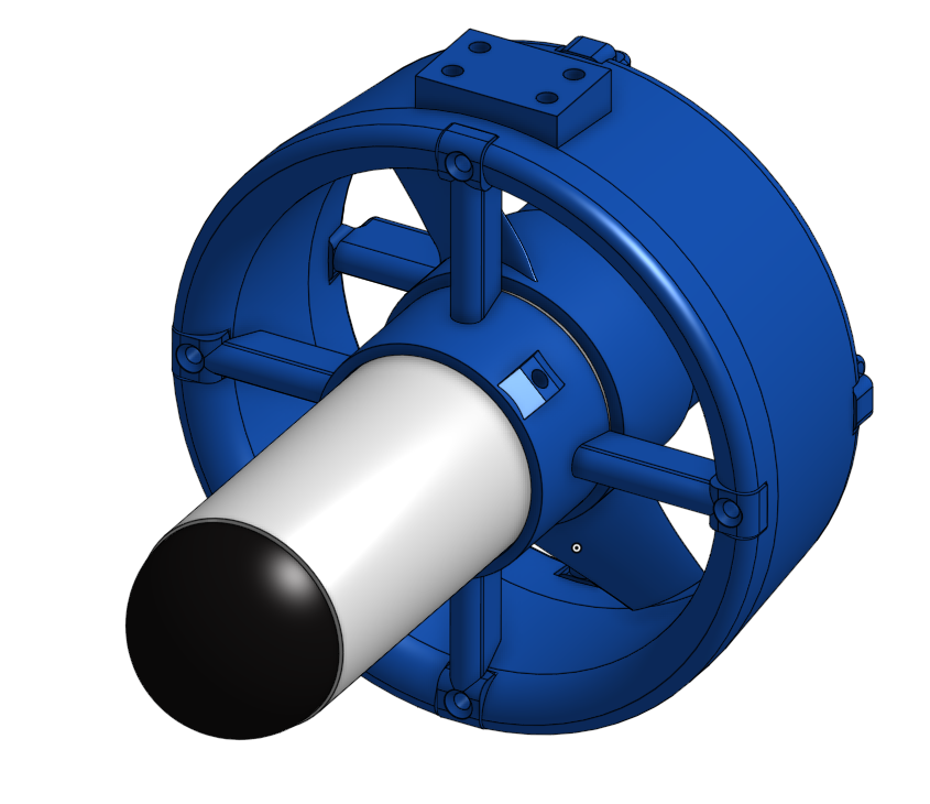
CAD Designs
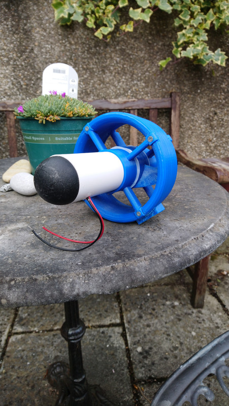
The finished thruster (needs a connector wiring up and sealing the ends of the wires)
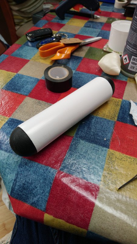
The motor housing without the prop or guard
I have designed and made my own thruster for Stingray, my ROV-in-progress. It was quite a challenge since not many people seem to have used magnetic coupling successfully. It's design was partly influenced by my manager, who suggested the idea to me. I also looked at the (very few) YouTube videos of various designs, as well as Steve's designs from the Homebuiltrovs.com main website. I used a ring-shaped prop design, with 8 neodymium magnets (north-south alternating polarity) glued in with epoxy. These lock in to the 8 corresponding magnets in the rotor, inside the main housing. One of my main concerns when designing the magnetic coupling was how much force the magnets would be able to transmit before slipping, but after a bit of trial and error, It takes a surprisingly large amount of force to cause the magnets to slip!
The main housing is PVC pipe (43mm OD), and the end caps are large dome-shaped furniture feet (with O-rings sealing the water out). A cheap brushed DC motor resides inside the main housing. the ring-shaped prop simply slides over the PVC pipe and locks on to the magnets. The prop guard and spokes slide on to the main housing in a similar fashion, securing in place firmly with two grub screws (although they fit fairly tightly without the grub screws). All of the light blue (internal) parts in the CAD pictures are 3D printed in PLA, and the dark blue (external) parts are printed in PETG.
I cheated a bit for the prop design - I used the blade profile of the Blue Robotics T100 thruster. I figured it would be a good idea to use blade profiles from someone who has qualifications in fluid dynamics!
The spoke parts also act as thrust bearings, stopping the prop from shooting off! I used a thin Teflon sheet for reducing friction between the prop, thrust bearings and the PVC pipe. This worked better than expected, and is very simple and easy to make. The prop and Teflon discs can be easily removed and cleaned/replaced in just a few minutes, which should prove useful for maintenance in the field.
The thruster makes about 250g thrust (although my testing methods were questionable, so it may be more). Obviously this can't exactly compete with professional thrusters, but I think it should be sufficient for Stingray. It only uses 0.6A at 24V. There is definitely potential for more power in the future!
I am currently in the process of printing the parts for the remaining three thrusters, then I can mount them to Stingray!
CAD Designs
The finished thruster (needs a connector wiring up and sealing the ends of the wires)
The motor housing without the prop or guard