Some of you may know about these, but I just found them. This is mostly likely the design I will be going with when I finish my ROV.
I will be using this gripper: http://www.crustcrawler.com/products/gr ... hp?prod=13
It can use a Hitec HS-645MG servo, which I will be waterproofing, as seen here:
http://www.youtube.com/watch?v=YWncPVO1o7s
A cool feature of this gripper is that it has a mounting plate above the gripper "fingers" to mount a light or secondary camera. The gripper is also made out of anodized aluminum, so it will not rust or degrade. I will probably mount it on the end of a PVC tube and have it sticking out the front of my ROV. I might even use a second servo to have a rotating wrist function. This video is a good example: http://www.youtube.com/watch?v=X_15aucM5Pc
It would probably be a good idea to upgrade the stock plastic servo horn for the wrist servo with an aluminum horn like this one: http://www.servocity.com/html/standard_hub_horn.html
My Gripper solution
-
fireslayer26
- Posts: 81
- Joined: Feb 6th, 2012, 9:36 pm
- Location: Florida, USA
- Contact:
Re: My Gripper solution
I have a similar gripper which i converted for motor drive from a small pond pump.
I did toy with waterproofing a servo but figured this would need more than just grease around the output shaft for any decent depth.
if you could fit a shaft seal to the servo this would be great. you could even oil fill it as long as you allow for changing the oil when it gets carbon in it from the brushes.
kepp us posted on how you get on fireslayer.
-
fireslayer26
- Posts: 81
- Joined: Feb 6th, 2012, 9:36 pm
- Location: Florida, USA
- Contact:
Re: My Gripper solution
Not a bad looking gripper. I just don't like that it needs 2 servos to operate.
Re: My Gripper solution
search around on thingiverse, there are several grippers on there you can down load and have printed.
-
fireslayer26
- Posts: 81
- Joined: Feb 6th, 2012, 9:36 pm
- Location: Florida, USA
- Contact:
Re: My Gripper solution
*New plan*
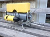
For the gripper, I will be using a Linak Linear actuator model LA12 to control the action of a toy robot claw as seen below. I will remove the yellow handle part of the claw and bend the metal push rod and attach it to the actuator, which will be placed inside a waterproof container.


According to the data sheet here: http://www.aketon.ru/files/catalogues/o ... 12_eng.pdf on page 5, I have the Actuator with absolute positioning in Figure 3. It looks like Black = Negative, Green = Positive, Yellow = signal, Red = Motor positive, Blue = Motor Negative?
For the gripper, I will be using a Linak Linear actuator model LA12 to control the action of a toy robot claw as seen below. I will remove the yellow handle part of the claw and bend the metal push rod and attach it to the actuator, which will be placed inside a waterproof container.
According to the data sheet here: http://www.aketon.ru/files/catalogues/o ... 12_eng.pdf on page 5, I have the Actuator with absolute positioning in Figure 3. It looks like Black = Negative, Green = Positive, Yellow = signal, Red = Motor positive, Blue = Motor Negative?
-
fireslayer26
- Posts: 81
- Joined: Feb 6th, 2012, 9:36 pm
- Location: Florida, USA
- Contact:
Re: My Gripper solution
I'm not good with wiring diagrams, so how would I wire up this actuator according to page 7 of this pdf:
http://www.promsnab.info/catalogues/linak/actuators.pdf
http://www.promsnab.info/catalogues/linak/actuators.pdf
-
thegadgetguy
- Posts: 238
- Joined: Feb 13th, 2011, 8:27 pm
- Location: Pennsylvania
Re: My Gripper solution
Red and Blue will be where you attach your motor controller (relay, etc.). Black and Green will need to be respectively at 0 and 5 Volts(or other reference voltage of your choice). Yellow will connect to your microcontroller or other circuitry. The voltage level on the yellow wire will correspond to the extension of the actuator. If you aren't using a microcontroller, you may want to consider the model with the reed switches and set something up with relays.
- Attachments
-
- Temp.PNG (9.27 KiB) Viewed 35579 times