I ordered a bunch of auto style relays with the pigtail sockets. To use with my on board batteries. I know i need 2 to reverse each of my thrusters. Digging around online i found this diagram for reversing car windows and figgered it should work the same for my situation. But no! unless im going crazy i have it wired up identical to the diagram. But as soon as i hook up to the power both relays click on and the switch wires do nothing( no switch for now just clicking the wires together).
One thing that does'nt seem right to me is that they have the 87a wires going to the switch but on my pigtails that is the heavy wire that in my view should be going to the motor. But maybe im getting this all wrong in my head.
thanks for any info
ps: any one else have a better diagrame?
auto relays
-
greenkarson
- Posts: 36
- Joined: Jun 5th, 2011, 9:21 pm
auto relays
- Attachments
-
- 3-Wire-Switches-2-Wire-Moto.png (8.36 KiB) Viewed 1885 times
Re: auto relays
A lot is going to depend on the layout of the pins on the actual relays you have.
-Steve
-Steve
Re: auto relays
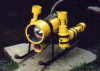
I'm going to assume the relay looks like this:

you don't want the motor current flowing through the switch - that is the whole point of using the relay. the switch should just be applying voltage to relay coils (terminals 85 and 86). only one relay should be on at a time. the relay isn't polarized - it doesn't matter if 85 or 86 are grounded.
so, terminal 85 of both should be grounded like you show. the up and down wires should go to terminals 86. that will energize the up relay when the switch is pushed up and the down relay when the switch is pushed down. the way you have it now, both relays are energized all the time.
30 is the common, and it looks like you have it hooked up to the motor correctly.
the other two terminals (87 and 87a) are going to supply the voltage to the motor. ground 87a on both relays. 87 on both relays should go to 12v.
after you wire it up and build the rov, if you find the thruster operates backwards, just reverse the wires going to the motor.
-
greenkarson
- Posts: 36
- Joined: Jun 5th, 2011, 9:21 pm
Re: auto relays
Thanks for all the info. My relay pins are laid out just like the relays in the diagram.
Derelicte, Thanks for explaining it all. I knew that i did'nt want the motor current going through the coil side of the relay. Thats why this diagram never made sense to me.
I guess just because someone has drawn something all pretty does not mean its right. Makes me wonder how many other people have found this diagram online and went nuts trying to figger it all out.