Pool ROVer

What are you working on .... Show off your Rov's Projects here.
derelicte
Posts: 292
Joined: Aug 1st, 2011, 3:08 pm

Pool ROVer

Post by derelicte »

Hello,

Our ROV started as a solution to an annoying problem:

Kids leave toys at the bottom of the pool. Scooping them out one at a time with the skimmer is boring and tedious.

Solution:

Build a ROV that can scoop them up faster, more efficiently and much more enjoyably!

Here is what we (my 5 year old daughter and I) have created. I call it the Pool ROVer:

Image

The basis for our rov came from Steve and his "A Little Sneak Peek..." rov:
viewtopic.php?f=18&t=74

The primary design goal was to build a self contained rov that didn't require a computer, video monitor, power supplies, etc. I think we met this goal. All power and control electronics reside in a water resistant food storage box above the water. The only wire to trip over is the tether between the rov and this box.

The frame is constructed of 1/2" schedule 40 PVC. The dimensions are 10" wide x 10" tall x 12" long. The buoyancy tubes are 2" pvc and extend about 1" above the top of the frame. The three thrusters are Johnson bilge pump cartridges with Traxxas RC boat props. The plastic netting around the frame allows us to "drive" around on the bottom of the pool and scoop up the toys.

The tether consists of three 18 awg speaker wires (one per thruster) covered with yellow techflex. Buoyancy is accomplished with 2" sections of pipe insulation wire tied at 1.5' intervals. The overall length of the tether is approximately 30'.

I'm most proud of the controller. The rov is controlled with a wireless Wii classic controller. This allows us to roam around the pool and drive the rov without tripping over wires. The controller's wireless receiver is connected to an Arduino which handles all of the motor control, controller initialisation and fault detection. Three 9 A motor drivers allow proportion, bi-directional control of each motor. Power comes from an internal 3 cell Lipo or an optional external 12 V UPS battery (for longer missions).

Finally, the ROVer is equipped with a video camera and light so we can watch our pool cleaning "missions" afterwards. The video is recorded on a micro SD card in the camera, so we don't get live video while we are operating the rov. Since we are using this in a 8-9' deep pool with crystal clear water, lack of live video isn't an issue.

Below you will find more detailed information about each of the major systems for the rov.

I'd like to add that this website made our project possible. Without all of the user contributions in this forum as well as the detailed information from Steve on the main site, we never would have been this successful this quickly.

THANK YOU!
Last edited by derelicte on Sep 3rd, 2011, 3:19 pm, edited 2 times in total.
derelicte
Posts: 292
Joined: Aug 1st, 2011, 3:08 pm

Re: Pool ROVer

Post by derelicte »

The frame is constructed from 1/2" schedule 40 PVC tubing. There are holes drilled in the frame to allow it to flood. I don't have any fancy 3d models, so old fashioned pictures will have to do. :D

Front view:
Image

Rear view:
Image

Left view:
Image

Right view:
Image

I spent quite a bit of time playing with the layout of the frame on the workbench. I knew I had to keep the bottom of the front open for scooping up toys. Everything else kind of flowed from there. I haven't gotten around to gluing the frame together. The sections are just pressed all the way into the joints and are pretty difficult to take apart. I am hesitant to glue it because my skills at gluing pvc pipes together aren't that great and I can't find any slow setting pvc glue locally. It will probably stay this way forever.

The two buoyancy tanks are built from 2" schedule 40 PVC tubing. I initially used 1.5" tubes, but they proved to be too small. The tanks are also just pressed together (no glue) and the screws that hold them to the frame are not sealed. So far there isn't any water in them, but I should probably glue and seal these tanks some day before they start leaking. At 9' deep (~4 psig), the pressure isn't a huge problem.

The black plastic netting surrounding the frame acts as a scoop to pick up the toys. It also doubles as protection for the props should the kids get a little too close. It is pulled tight around the frame and held in place with lots of wire ties.

Image

To trim the buoyancy of the rov, I have 1/2" stainless steel rods inserted in the front vertical frame tubes. With the camera and light installed, the rov is just slightly positively buoyant. As you can see in the following picture, the rov is slightly nose heavy and still needs to be fine tuned.

Image

I have a bunch of the 1/2" stainless rods cut to different lengths for just this purpose. I just need to pull the frame apart to find the right combination (another advantage of not gluing the frame!).

Update 1 (9-7-11):
I took the buoyancy tanks apart and found a little water in them so I glued the caps on and applied caulk to the screw holes before I remounted them. Hopefully that will prevent water intrusion in the future.
Last edited by derelicte on Sep 7th, 2011, 4:07 pm, edited 2 times in total.
derelicte
Posts: 292
Joined: Aug 1st, 2011, 3:08 pm

Re: Pool ROVer

Post by derelicte »

The rov's propulsion is provided by three thrusters: two mounted horizontally and one vertically. The horizontal thrusters are 500 gph Johnson bilge pump cartridges. The vertical thruster is a 1000 gph Johnson bilge pump cartridge. In this application, the sizes chosen work pretty well. However if I were to replace any of them, I'd consider upgrading the horizontal ones to 750 or 1000 gph ones. You can never have too much power!

Image
http://www.westmarine.com/webapp/wcs/st ... sNum=10627

Image

The thrusters are mounted to the frame with plastic 1.25" conduit clamps with shims made from pvc pipe to remove the gap. The fit is very tight and this arrangement works quite well.

Image
Image
Image

The props come from a Traxxas Villian EX RC boat. They are 47mm in diameter (pitch unknown) and have a M4 threaded brass insert with a stainless set screw to lock it to the shaft. They can be found in hobby stores and at Tower hobbies in left hand and right hand versions.

Image

Right hand prop:
http://www3.towerhobbies.com/cgi-bin/wt ... LXGBH1&P=0

Left hand prop:
http://www3.towerhobbies.com/cgi-bin/wt ... LXGBH0&P=0

Initially I tried making a shaft adapter from this shaft coupler:

Image
http://www3.towerhobbies.com/cgi-bin/wt ... LXTTR9&P=0

However without a lathe at my disposal, I made a mess out of two of them. A co-worker with a lathe was able to drill one out for me, but ultimately it proved unnecessary. It turns out these props fit perfectly on the bilge pump motor shafts without any adapters! There are even flats spots on the shaft for the set screw. I'd suggest that you apply a little blue loctite to prevent the set screws from working loose, though.

Image

I chose to use counter-rotating props for the horizontal thrusters. Looking at the rov from the back, the right prop spins clockwise (the normal rotation) while the left one spins counter-clockwise. The rov tracks perfectly straight in forward and reverse without any tendency to roll.

Unfortunately the same is not true for the vertical thruster. With only a single prop (right hand prop), the rov will spin around the vertical axis when the vertical thruster is running. The yaw is easy enough to correct with the controller, but I'd prefer that I didn't have to. I'm currently working on a solution using the horizontal thrusters to correct the yaw. Watch this space.

Underwater at full speed, each horizontal thruster draws approximately 4 amps max. The bigger vertical thruster draws about 5 amps max. I have no way to measure the thrust, but I can say the rov moves around the pool at a pretty good clip. It can also lift a half dozen toys off the bottom at once.
Last edited by derelicte on Sep 7th, 2011, 4:10 pm, edited 3 times in total.
derelicte
Posts: 292
Joined: Aug 1st, 2011, 3:08 pm

Re: Pool ROVer

Post by derelicte »

Control of the rov is handled by a microcontroller. This allows for more precise control, greater functionality and ease of use over relays and switches.

Some of the features currently built into the controller include:

1. Fully proportional, bidirectional control of all three motors
2. Mixing of horizontal thruster power so that left/right/forward/reverse is controlled by one thumb stick
3. Adjustable hover trim with one button enable/disable toggle
4. Yaw control with adjustable trim
5. Low and high speed range select
6. Low voltage warning and cut off (very important for Lipos)
7. Fault detection
8. Status indicator

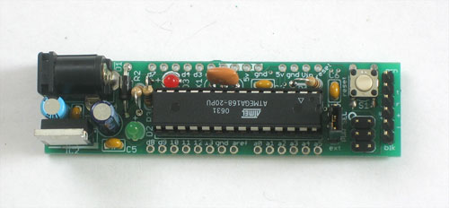
The controller for the ROVer is based on an Arduino clone called the Boarduino:

Image
http://www.ladyada.net/make/boarduino/index.html

The arduino is an open source microcontroller development system. It is fairly inexpensive, pretty powerful and very well supported. You can make almost anything you can imagine with an arduino.

Arduino info:
http://arduino.cc/

I chose the boarduino because I happened to have one lying around from a previous project that was no longer in use. Also, the form factor is a little easier to work with due to the pin spacing. It fits perfectly in the motherboard I built for it based on a standard radio shack PC board. The code will run correctly on any official or unofficial arduino clone without any changes.

Image
http://www.radioshack.com/product/index ... d=2102845#

The motherboard has all of the support components (power supply, resistors, etc.) and the connectors for the motor controllers and Wii controller.

Image
Image

There are two motor controller modules, a single for the vertical thruster and a dual for the horizontal thrusters. Each motor controller has a 16V max and a 9 A continuous current rating with a peak current rating of 30 A. They also have fault detection and a couple of other cute features. At the currents I am drawing, it doesn't need a heatsink, however I already had one installed on the single motor driver (left over from an older project). I probably won't bother installing them on the other two.

Single motor controller:
Image
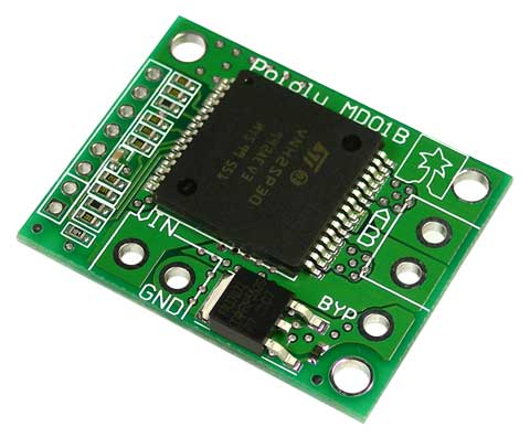
http://www.pololu.com/catalog/product/705

Dual motor controller:
Image
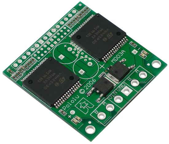
http://www.pololu.com/catalog/product/707

The user interface for the rov is a wireless Wii classic controller called the Wing from Nyko:

Image
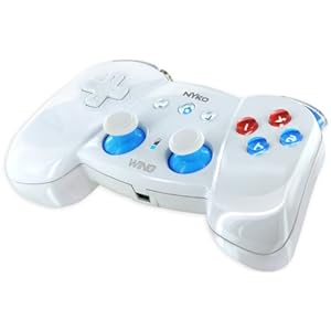
http://www.amazon.com/Wing-Wireless-Con ... 744&sr=8-1

The Wing has a little receiver that normally plugs into the Wiimote. It is the little white box in the picture above. In my application, it is connected to the arduino. Initially I started with the wired Wii classic controller pro, but the short cable caused issues with seeing the rov and the kids were always tripping over it. The wireless version eliminates these issues. It has a stated range of 10', but I have used it more than 20' from the receiver without issue. I can walk anywhere around the pool and still control the rov. The only negative about this controller is the buttons have a very mushy feel to them. The wired controller has much better buttons along with a slightly better position for the shoulder buttons.

There is a arduino library for wired controller that makes using the Wii classic controller a snap, however it doesn't work with the wireless one. It took quite a bit of reverse engineering and googling to get it working.

The right stick controls the forward/backwards/left/right movement of the rov. The mixing of the left and right thruster power levels is calculated by the arduino. For example, if you push the stick all the way up, then both motors spin forwards at full power. For full left, the left thruster spins backwards at 100% and the right spins forwards at 100%, and so on.

At full speed, the rov is pretty fast so to make the rov easier for the kids to drive it has two speed ranges: low and high. Low speed limits the power to 50% with high speed allowing 100% power. Only the horizontal thrusters have the low and high speed. By default, the rov is in low speed mode. High speed mode is enabled by holding down the right shoulder button.

The left stick on the controller controls the vertical thruster. Pushing the stick up causes the rov to rise in the water. Pushing the stick down causes it to descend. The rov can be set to hover at any depth by pressing the up and down directional pad buttons. Basically you press the down button until the rov stops rising. The left shoulder button enables and disables the hover. This is handy when you come to the surface to retrieve the toys and don't want the vertical thruster spinning. You hit the button to shut it off, get out the toys, stick it back in the water and hit the button again to turn it back on. It remembers the last setting so you don't need to readjust it. Perfect buoyancy at the touch of a button!

The only downside to having a single vertical thruster is the rov will spin (yaw) when the thruster is moving. A gyro would easily solve this issue, but I don't want to install one on the rov. Therefore I have tried to emulate a gyro in software with what I call yaw control. The arduino knows the speed and direction of the vertical thruster, so it can apply a counter-acting yaw command to the horizontal thrusters. That is the theory, anyway.

I tried a few different ideas for correcting the yaw. The first involved multiplying an adjustable gain to the vertical motor power to come up with the left and right correction powers. This didn't work real well and also revealed another problem: the direction of the unwanted yaw was dependent on the direction of the vertical thruster (duh!). My next idea (which I never actually implemented completely) was a look up table with different corrections stored for a fraction of the vertical powers. This would probably provide the best correction, especially if the yaw is non-linear.

The final approach that I tried was I simply assumed that yaw was linear. I determined the amount of correction needed for full up power and full down power and use these as limits. The vertical motor power is scaled to come up with the correction. This technique worked well enough that I have stuck with it. The yaw is definitely not linear, but the deviation is pretty small and not worth implementing the look up table to correct. The other observation I made is the props I have used generate more thrust in one direction than the other.

In order to help determine the amount of correction, I modified the arduino code to print out the motor powers when I pressed a specific button. This allowed me to log the correction needed for full up power and full down power. The left and right direction buttons control the limits of the yaw control used for the scaling which allows for fine tuning while the rov is in use.

The home button on the controller resets the settings and stick center positions. This is handy if you get the trims way out of whack. The rest of the buttons are currently unused.

The electronics are housed in a clear, waterproof food enclosure.

Image
http://www.bedbathandbeyond.com/product ... 75&RN=204&

Overhead view:
Image

The Li-Po battery is the blue rectangle at the bottom. There is a lighted power switch on the left side of the box and a fuse holder (slightly obscured) above the battery. The arduino is in the center, the dual motor controller is on the left of the arduino and the single motor controller is on the right. The tether connector is the right side of the box. The Wing receiver is the white square attached to the side of the box at top of the picture.

The arduino and the motor controller assemblies sit on a foam cradle:
Image

Switch side:
Image

Tether connector side:
Image

Cover on and ready to go!
Image
Last edited by derelicte on Jan 12th, 2012, 10:19 am, edited 6 times in total.
derelicte
Posts: 292
Joined: Aug 1st, 2011, 3:08 pm

Re: Pool ROVer

Post by derelicte »

The tether was the source of most of my frustration for this project. My goal was to find something to encase the wires and provide buoyancy without getting hung up on itself. I'm still not there. I have the encasing part solved, but not the buoyancy part. This is a work in progress.

The tether consists of three pairs of 18 awg speaker wires (two conductors per pair, six conductors total).

Image
http://www.monoprice.com/products/produ ... 1&format=2

The clear insulation has the added benefit of allowing me to see if any water has entered the insulation and corroded the wires. The wires are soldered to the thruster wires and covered with marine grade waterproof heat shrink tubing.

Image
http://www.westmarine.com/webapp/wcs/st ... sNum=10612

Image

Because the depths we are going to aren't very great, I chose this route as an easy way to splice the wires together without having to seal the wires going into and out of a waterproof housing. So far, the waterproof heat shrink seems to be working quite well. Time will tell...

I tried various sheaths and buoyancy methods before arriving at this solution. Things I tried include:

1. 2" sections of pipe insulation wire tied at 2' intervals (perfect buoyancy but zero protection; bulky and got hung up on itself)
2. 6" "slivers" of pipe insulation wire tied to wires (again zero protection, perfect buoyancy but a little less likely to get hung up)
3. 1/2" hollow braided polypropylene line (provided zero buoyancy and was impossible to thread the wires through)
4. 1/2" polypropylene rope wire tied to wires (no protection and didn't provide enough buoyancy)

Ultimately I used about 30' of 3/8" yellow techflex wire covering purchased from ebay to wrap the wires.

Image
http://cgi.ebay.com/ebaymotors/3-8-EXPA ... 35b35aaf17

The techflex provides zero additional buoyancy, but it protects the wires, keeps them together and isn't too hard to thread the wires through it. However I still need additional buoyancy to keep the tether from sinking. For now I have 2" sections of pipe insulation wire tied at 1.5' intervals. The downside is the insulation can cause the tether to hung up on itself. My next iteration may be to use foam backer rod as floatation.

Image

The tether is secured to the rov with two wire ties. This may not be the best solution, but so far it seems to work ok.

Image

Topside, the wires are terminated with a waterproof connector from Molex:

Image
http://www.molex.com/molex/products/fam ... connectors

Image

This allows me to separate the rov from the control box for easier storage, untangling the tether, etc. Regular heat shrink tubing covering the end of the techflex ends prevents it from fraying and neatens it up a bit.

I'll update this post when I arrive at the final solution.
Last edited by derelicte on Sep 3rd, 2011, 3:43 pm, edited 2 times in total.
derelicte
Posts: 292
Joined: Aug 1st, 2011, 3:08 pm

Re: Pool ROVer

Post by derelicte »

The camera used on ROVer is commonly called the 808 key chain camera found on ebay for <$10.

Image

You want the #3 version of this camera. There are a lot of knock off versions of this camera on ebay, some are about the same quality wise, some are not as good. For the best up-to-date info refer to these sites:

http://www.chucklohr.com/808/
http://www.rcgroups.com/forums/showthread.php?t=1115052

The camera is completely self-contained. It records 720x480 video on a micro sd card inserted into the side. It has an internal battery that can last quite a long time. All we do is turn it on, stick it in the housing, close up the housing and mount it on the rov.

There is also a HD version of this camera available for about $40.

http://www.chucklohr.com/808/C11/index.html
http://www.rcgroups.com/forums/showthread.php?t=1362692

Initially I tried making a housing from a 1.5" union, but the result was a really heavy assembly that had a huge frontal area (over 3.75" in diameter!). I went back to the hardware store and searched around for a more compact solution assembled from bits of different pvc fittings.

Image

The main part is a 1.25" slip fitting with a threaded cap glued on the end. The lens is a polycarbonate disc cut to fit inside the threaded nut. An o-ring provides the seal between the housing and the lens. A co-worker with a lathe milled a groove into the end to capture the o-ring and provide a better seal. Finally, a flat rubber washer sits between the lens and the nut which prevents the nut from coming loose underwater (this has actually happened a few times during development).

The camera sits on a platform made from a smaller piece of a 1/2" pvc tee cut to fit. A small piece of pipe insulation wedges the camera firmly in place.

Image

The wire tie sticking out underneath the camera provides a little tab to pull the camera out from the housing.

The housing slides into an adjustable retainer made from a 1/2" snap-on saddle tee mounted on the rov.

Image
Image
Image

Illumination is provided by a small diving light:

Image
http://www.westmarine.com/webapp/wcs/st ... sNum=10587

The light snaps into a 3/4" threaded pvc tee that I cut to fit. This is threaded into another 1/2" snap-on saddle tee that allows the light to be adjusted and aimed as needed. It is not permanently attached so it is also removable. It just snaps on and off like the camera retainer.

Image

Also, because it is removable, the placement is flexible.

Image

I'm still experimenting with the best location.

One final shot of the camera and light mounted and ready to go!

Image

Here are a couple of frames from the video to show the quality. It is pretty good for <$10!

Image
Image

Update:

I have replaced the SD keychain camera with the HD version. It is exactly the same shape and size as the SD version, so it fits perfectly in the housing.

Image
Image

Note: these images have been resized by the hosting site. The original resolution was 1280x720.

The HD camera has better color rendition along with the higher resolution than the SD version. It also requires a larger micro SD card to be usable. I bought a 4 GB card use in it. It will support larger cards, but the built in battery will die before it can fill a larger card (about 20 minutes). I also added a little foam spacer behind the camera (not shown in the exploded picture above) to keep the camera from sliding back into the housing. The widescreen lens was seeing part of the housing in the corners if the camera got pushed back too far.
Last edited by derelicte on Jan 12th, 2012, 10:34 am, edited 7 times in total.
derelicte
Posts: 292
Joined: Aug 1st, 2011, 3:08 pm

Source Code

Post by derelicte »

Here is the Arduino source code for the Pool ROVer. This code has been compiled for ardiuno ide version 1.0. It may also work with other versions, but I make no guarantees.

The first piece of software is the Wii classic controller and Wing wireless controller library. Extract the folder into the arduino libraries dirctory. This file is largely based on the work of others. My contribution is in the initialization routine to add supprot the Wing controller. This library supports both the wired classic controller as well as the Wing wireless one. It can automatically detect if the data needs to be decrypted and decrypts it.

Extract the poolrover folder into your sketchbook directory. There are a couple of debug flags that print out status to the terminal so you can see what is going on. All of the pin assignments are in the .h file.

Have fun!

Revision history:

Rev 1.0: Initial release.
Attachments
poolrover1_0.zip
Pool ROVer 1.0 arduino source code
(3.47 KiB) Downloaded 604 times
WiiClassic.zip
Arduino Wii classic controller library
(2.21 KiB) Downloaded 1292 times
Last edited by derelicte on Jan 31st, 2012, 9:47 pm, edited 1 time in total.
User avatar
Pilikia
Posts: 65
Joined: Nov 13th, 2010, 2:40 am
Location: Kauai, Hawaii
Contact:

Re: Pool ROVer

Post by Pilikia »

Nice job! Very clear presentation of objectives and solutions. And clever to reserve space for fleshing out project.

I'm a bit confused about, "The tether consists of three 16 awg speaker wires (one per thruster)..." I thought a ground wire of a similar size is needed to complete the circuits. Evidently not. What am I missing? How does this work?

I will be nice to see pictures from angles that show the thrusters.
derelicte
Posts: 292
Joined: Aug 1st, 2011, 3:08 pm

Re: Pool ROVer

Post by derelicte »

Thank you for your comments!

Each speaker wire has a pair of conductors, therefore there are actually six individual conductors in the tether.

Sorry for the confusion.

I just did the camera and light section and I plan on documenting the rest of the project over this weekend if I get the time.
User avatar
SoakedinVancouver
Posts: 117
Joined: Dec 31st, 2010, 9:38 pm

Re: Pool ROVer

Post by SoakedinVancouver »

A Beauty! Well thought out and put together, kudos!

How often does your daughter now throw stuff in the water so as to get the ROV out?
Post Reply