The design I stumbled across was by
@EKMallon of The Cave Pearl Project, and mine is simply a modification of this. So first and foremost, all credit goes to him. Anyways, his design involves folding up wires inside these connectors which I found too tedious and finicky, and I just wanted a simple connector that could push together and be watertight. Enter, the waterproof XT30. Oh, also, please please read his blog post here: https://thecavepearlproject.org/2015/01 ... or-system/. This guide is very similar to his and he has some better images and details, so read both.
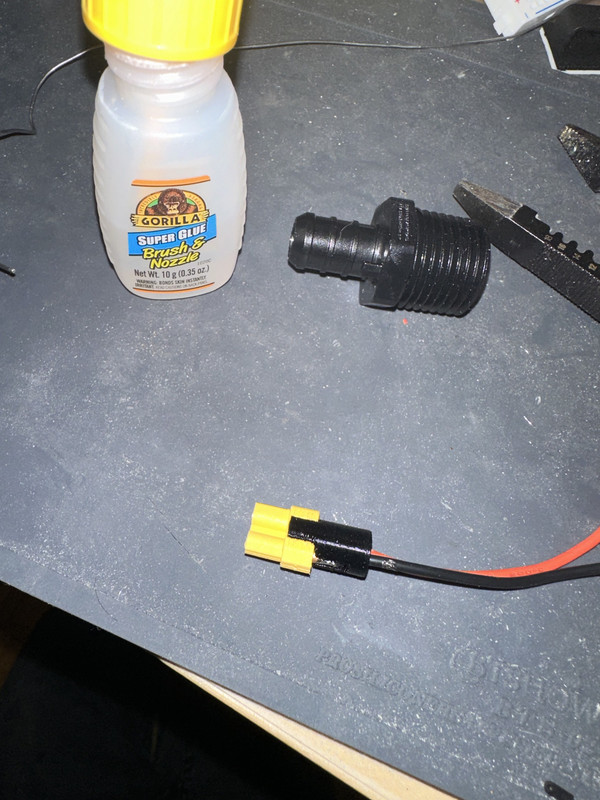
The basic concept is to use a 1/2" barbed x 1/2" mips plastic pex adapter and a 1/2" barbed x 1/2" fips swivel plastic pex adapter as a connector. Edward details the theory behind this design on his blog, but basically a rubber gasket is pressed into the male adapter to create a seal, and an electrical connector fits inside the pipe with the wires sliding into the barbed fitting. This whole thing is then filled with epoxy to create a removable, watertight connector. While experimenting with this, I discovered an XT30 connector fits perfectly inside either fitting, and decided to 3D print a clip that holds the connectors in place for a perfect fit every time.
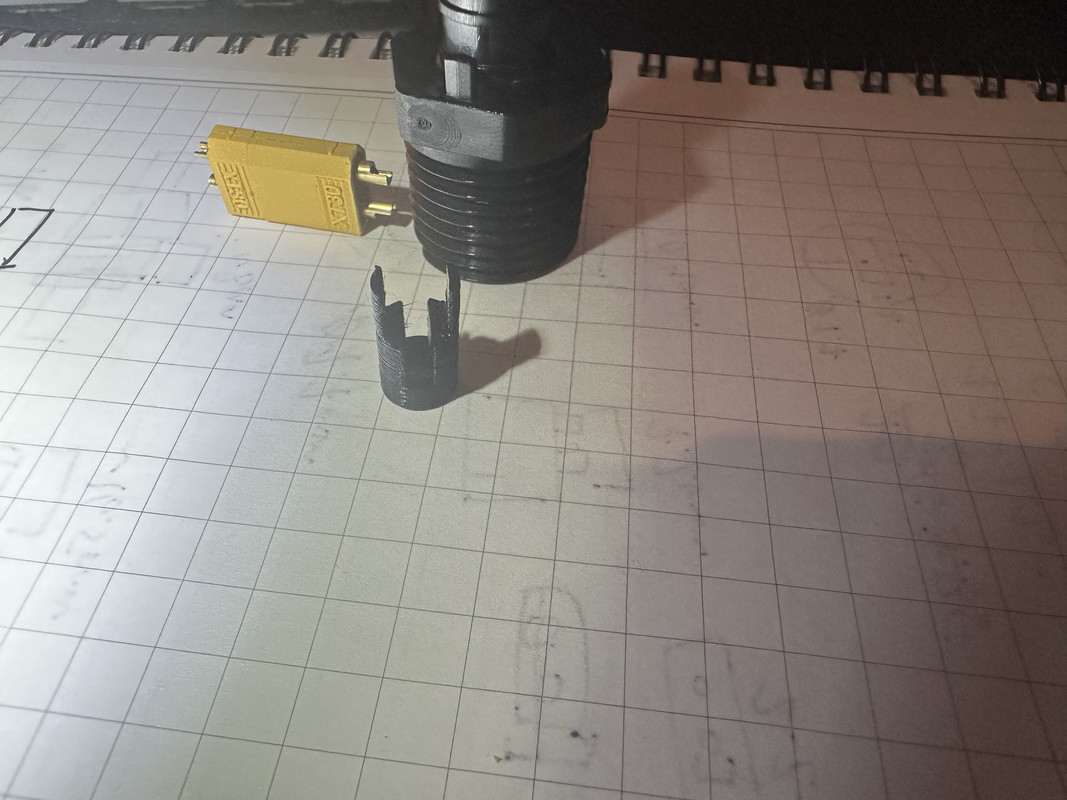
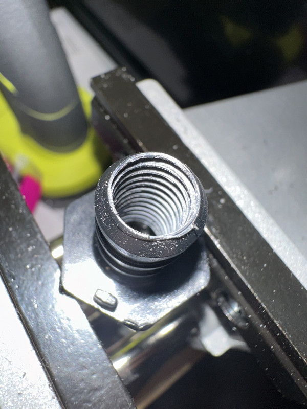
Pictured is the male adapter as well as the clip I 3D printed. You can see how it works below:
The clip sits inside the barbed inner hole and the connector sits inside the clip, which holds it in place.
So, step 1 is to print out 1 of these clips for each connector end, so one pair requires 2. I recommend printing a bunch of these as they're delicate. A link will be provided at the bottom of this post.
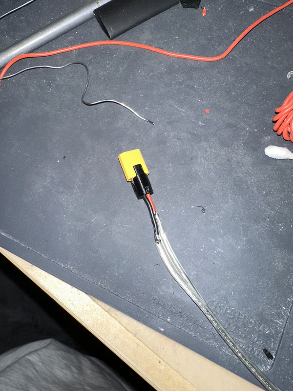
Step 2 is to prepare the connectors. I soldered 20 gauge stranded silicone wire onto each connector end. This would be my recommendation as well, though you may be able to fit 18 gauge stranded silicone wire through the clip, 20 gauge is likely enough for LED accessories or small motors. This can be a short length, but long enough to fit through the whole fitting with some room to solder on extensions, more on this later. Do NOT use heat shrink here, cut and strip your wires so they don't touch.
Here you can see the connector with the wires through the hole in the clip and soldered on. I also cut some insulation off at staggered locations to hopefully get some resin flowing into the strands for sealing purposes, though you can probably skip this as the solder joints being exposed accomplishes a similar goal.
Step 3 is to snap the connector into the clip, approximately centered across the wide face and all the way down in the clip.I recommend doing a dry fit then using a little dab of superglue just to hold it in place, this makes further dry fitting easier.
Step 4 is to prepare the fittings. From the OUTWARDS end of the BARBED connector on the fitting, use an 8mm (approximate) tap to create ridges inside the barb. This gives the resin more grip and mechanical strength inside the fitting. I used a 5/16 tap for some, and it was definitely too large. 8mm is a lot closer but to be honest, you could probably go down a size further and still get good results while being an easier tapping operation. I just grabbed the barb in some vise grips and *carefully* spun the tap in my drill.
Step 5, insert the clip, wires, and connector into the fitting, wires first through the inside (so the wires exit the barbed end).
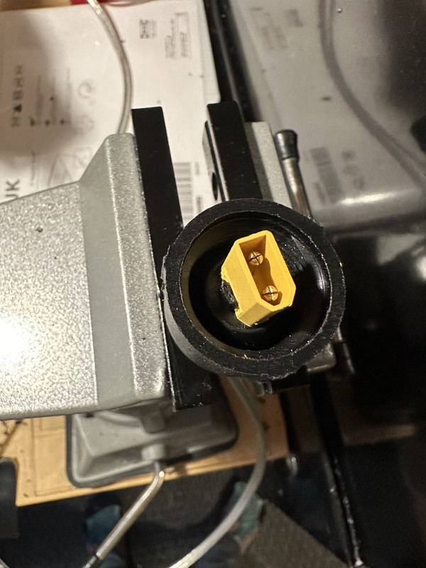
This isn't the best image but make sure the connector is centered inside and press it ALL the way down, so the back of the connector is flush with the base of the inside of the fitting.
Step 6, almost time to mix up the resin, but first, VERY IMPORTANT, prepare some lengths of WATERPROOF (meaning, adhesive lined) heat shrink. I used 3:1 ratio tubing, and the sizes were 3/8" and 1/2". Feel free to experiment, but you're looking for the SMALLEST size that will fit over the barb and then the BIGGEST size that will still compress fully around the wires. Using these two sizes, you'll later build up a few layers of tubing so that you can create a transition from the barb to the wires. NOTE: DO NOT INSTALL ANY HEAT SHRINK YET, JUST SET THESE SOMEWHERE NEARBY.
UP UNTIL THIS POINT, the instructions are the same for either the male adapter or the female swivel adapter. However, because the female swivel adapter end is going to be attached to an accessory and the male end is going to be epoxied to the hull, we need to think about the additional wiring for the female adapter. I recommend cutting a 3-4' length of whatever STRONG wire you plan on using for water-exposed connections. In my case, I'm using 18 gauge clear speaker wire. It's stranded, basically 2 conductors, and heavy enough gauge for my purposes. I may install a piece of vinyl tubing as armor, though that's TBD.
Anyways, back to the female fitting, mark with a sharpie where the already soldered wires exit the barb. Then remove the connector assembly from the fitting.
Step 7 is only required for the female fitting cable, but you must solder on any extensions so that the solder joints don't extend out past the barb (reference your mark from the last instruction). I staggered these two joints, and again didn't use any heat shrink.
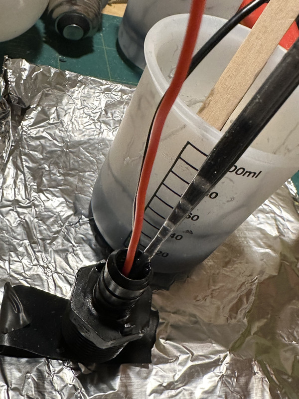
Reinsert the connector into the fitting, threading the long length of wire through the barb (MAKE SURE IT'S FULLY INSERTED). With the extension on the connector, it becomes more cumbersome, so before you add the resin slide the pieces of adhesive lined heat shrink onto the cable from the bare end.
Step 8, prepare your workspace for resin. I used a random craft grade 2 part epoxy resin from amazon. I believe genuinely almost anything would work, so feel free to experiment depending on your budget. The stuff I used seemed to be just about perfect but I'd reckon the thinner you can get, the better. You can probably do a pair of connectors comfortably with between 5-10ml of resin, TOTAL. I made 20 and was left with a huge ridiculous puck of resin. This is another area that requires more experimentation. I also added black pigment to mine, but this step is optional.
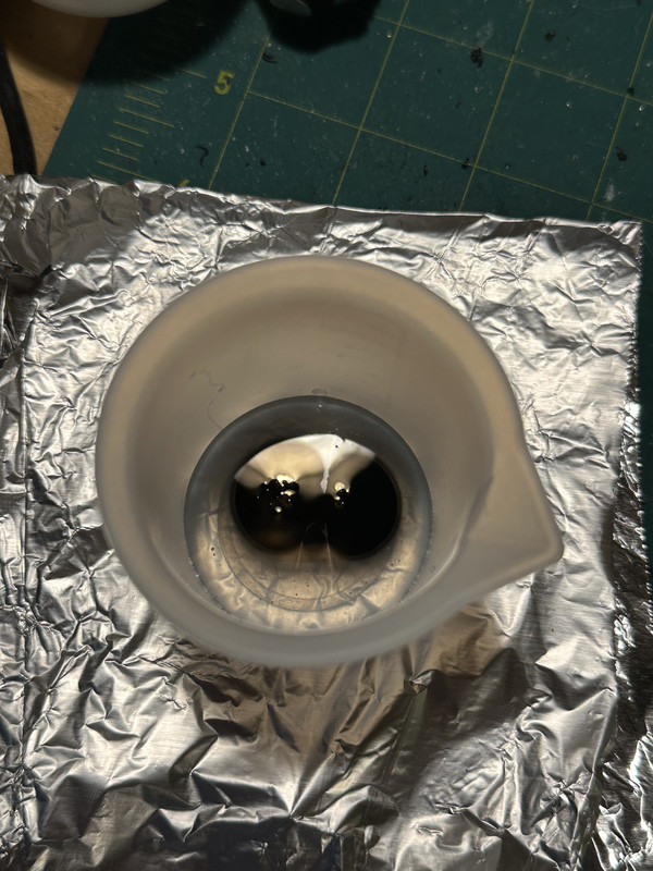
Step 9 is to fill the connectors with resin, starting from the outer end of the barb.
I used a cheap dropper that came with the resin kit, but the resin was too viscous to really use effectively. I'd probably get a real syringe and metal applicator needle when I do this again. NOTE, the male adapter end can just sit on the table as the XT30 is recessed inside the fitting, but the female swivel adapter will need to be held in a vise or clamp as the connector extends out past the fitting.
You want to fill each end with resin until they're topped up. I agitated the resin with an oscillating saw but in hindsight I'd recommend not messing with it at all beyond tapping it. This part is important, and it's also a little experimental and will vary, but I'd wait 60 seconds after potting the fitting before proceeding to the next side, because we want to let the fitting fully be penetrated by resin before we seal the other end. If you leave it too long, resin will start to seep out the other end, which while is a great indicator you've got full resin penetration, it is messy and could cause the connection to not fit. I luckily was able to save mine when this happened, but in the future you should definitely seal it up and flip it before this happens.
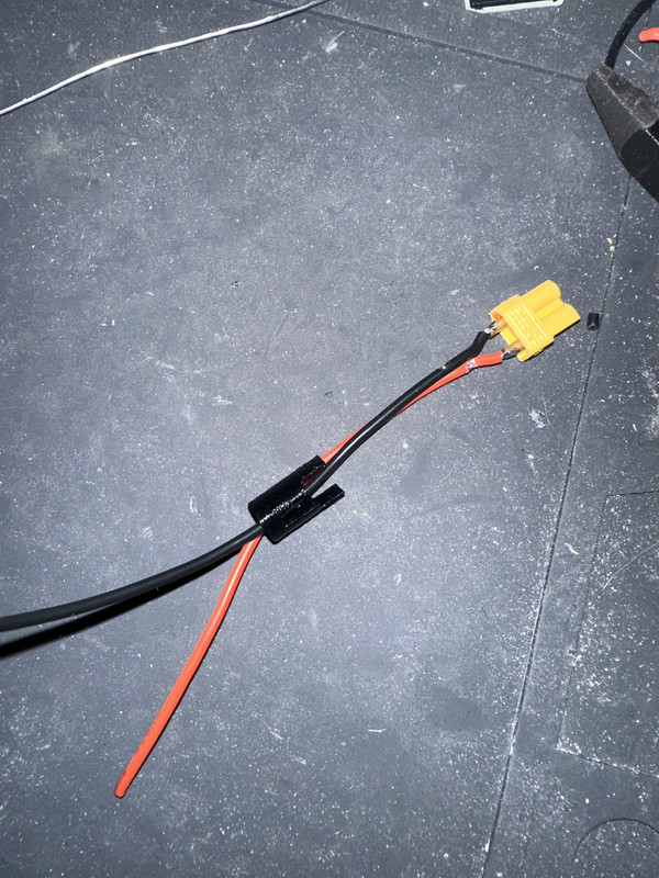
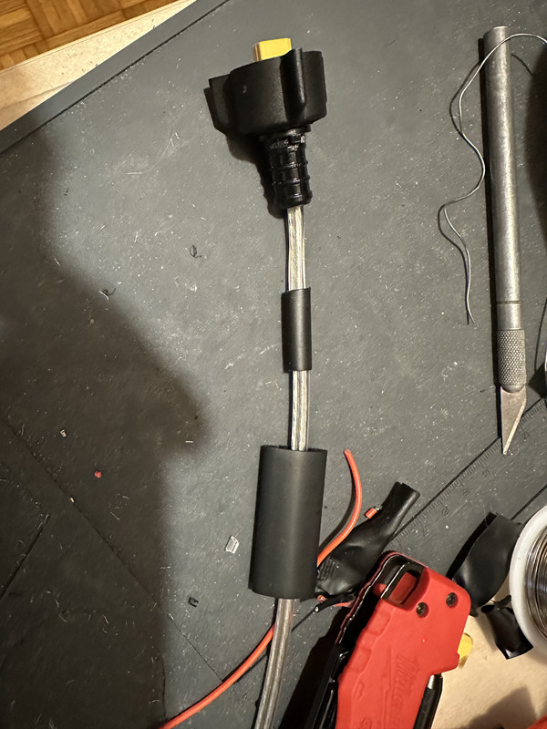
Sealing just involves installing the smaller pieces of heat shrink to build up enough thickness on the wires, then install the larger tube around the barb and wires/tubing. The glue should seal any resin from escaping out (and hopefully some water coming in)
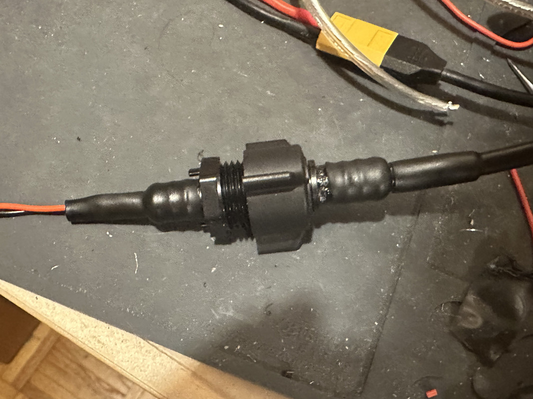
DON'T CONNECT THEM AT THIS POINT, this image is only meant to demonstrate how the heat shrink is installed. The left fitting is the inner hull version while the right is the external end.
After sealing up the wires, flip the fitting and carefully inject a small amount of resin around the fitting. Be very careful not to overfill and interfere with the xt30 connection, and for the female end with the rubber gasket, don't get resin on the rubber. This is where a nice precise applicator and thin resin really help.
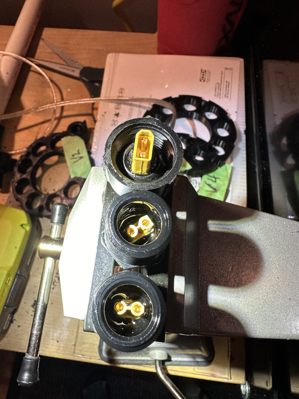
Monitor the fittings for leaking resin at the wire end, and fill them further if the resin level drops. At this point all types of fittings will need to be held up in a vise or clamp. Pictured are two male adapter ends and 1 female adapter end.
Step 10 is to let the resin cure, but not fully. Using unused resin as reference, wait until the resin is stiff enough to hold its shape, but still a little flexible and rubbery. For me this was about 6 hours later. At this point, I recommend connecting the two ends for the majority of the rest of the cure. If done this way, the connectors pull each other together and the resin will fully harden around them, retaining their orientation. Refer to the above image of the connectors screwed together. After about 24 hours undo the connection, and I'd highly recommend waiting an ADDITIONAL 24 hours, just so the resin can fully cure the rest of the way now that it has more air exposure.
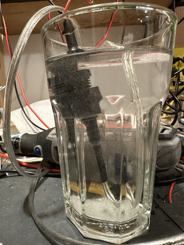
That's pretty much it. The male end can be inserted through a hull and epoxied in place acting as a port that the female end can screw into. I haven't yet pressure tested these, so use at your own risk, but I've had some submerged for 48 hours with no moisture indication on either the inside of the XT30 connector itself or the inside of the fittings. If you're paying attention, you may notice that the connectors have multiple, redundant sealing points. The wire insulation, multiple layers of heat shrink tubing and hot glue, the resin itself, the shielded nature of the connector (as well as the screw pressure forcing the connector closed, and then of course the same layers repeated for the other cable end. This just means that there are a lot of checkpoints for water to get blocked off by, meaning if a seal fails, damage will hopefully be minimized.
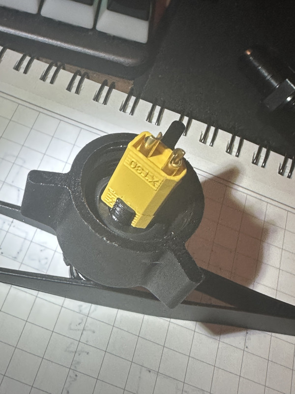
I also verified that there no shorts, nor non-trivial resistance in the connections, which there were not, and this means the connectors are fully and correctly seated. I wanted to visually inspect this to make sure though, so I sacrificed a set of connectors to double check. Any damage or marks on the connector are a result of my reckless dremeling, but if you look closely you can see the seam where the two connectors mate, and they're fully inserted.
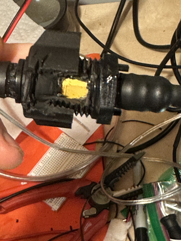
You can also see how the rubber gasket seals the swivel fitting onto the male adapter.
IMPORTANT INFO AND LINKS:
Which side should have the female and which side should have the male XT30 connector?
- This will vary occasionally, but the female end should be the supply and the male end should be the destination. I.E, if the connector was for a light, I'd use the male adapter, sealed through the hull, with a female XT30 end. The wire attached to the light would have the female adapter with a male XT30 connector. However, for an external battery, this connection would be inverted.
There's resin leaking through the fitting!
- This happened to me too. Very quickly seal your heatshrink on to the wire end and over the barb, and flip the fitting over. Excess resin can hopefully be cleaned up with a Q TIP or toothpick. As long as it doesn't harden onto the connector or seep inside the connector it's still savable.
How much pressure can this handle?
- I don't know, I don't have a vacuum testing rig, but Edward may have figured it out on his blog, I don't remember though. To be honest, my ROV will likely not descend beyond 50ft, so I'm kind of just hoping it will be fine to that depth. This answer also varies by resin choice.
Link to the supplies I used, not all are needed and feel free to bring your own.
- 2 Part resin kit: https://www.amazon.com/LETS-RESIN-Harde ... C88&sr=8-5
- 1/2 pex male adapters: https://www.homedepot.com/p/Apollo-1-2- ... /301541055
- 1/2 pex female swivel adapters: https://www.homedepot.com/p/Apollo-1-2- ... /301541052
- Link to the 3D model: https://www.thingiverse.com/thing:6340265/files