Rov Reboot (3D Printed Rov)

What are you working on .... Show off your Rov's Projects here.
User avatar
sthone
Posts: 589
Joined: Nov 8th, 2010, 9:25 pm
Location: Connecticut
Contact:

Re: Rov Reboot (3d Printed)

Post by sthone »

Camera Tube 48.jpg
Camera Tube 48.jpg (895.49 KiB) Viewed 44169 times
Well I got everything wired up and everything still works... the view shows whats next. :P

Even though this was just going to be a small observation Rov I still kind of planned on adding a small manipulator to it anyway. The only problem is I will only be able to control either the manipulator or the tilt for the camera at one time. I'm going to try and make the manipulator easily removable and with modular grippers.
Manipulator 01.jpg
Manipulator 01.jpg (646.11 KiB) Viewed 44169 times
This is a 50% version of the 3D Printed Manipulator I designed before...
ManipulatorDesign001.jpg
ManipulatorDesign001.jpg (143.87 KiB) Viewed 44169 times
... and this version will be a 3D printed design based off the gripper I made out of a Radio Shack Armatron that I used on my Seafox because I really like the parallel gripper design better I think.
ManipulatorDesign004.jpg
ManipulatorDesign004.jpg (86.16 KiB) Viewed 44169 times
The gripper design uses a worm gear setup just like the original Armatron. I added some hooks to the grippers tips to add some versatility so you could close them stick them in a hole and open the gripper to grab the item with the hooks.
ManipulatorDesign002.jpg
ManipulatorDesign002.jpg (155.03 KiB) Viewed 44169 times
The main arm and housing will be made from PVC Pipe and Fittings and use a shaft seal much like my Seafox manipulator. (The shaft is not shown in these diagrams.)
ManipulatorDesign003.jpg
ManipulatorDesign003.jpg (54.52 KiB) Viewed 44160 times
There are quite a bit of bits and pieces to this design because I am incorporating a clutch into the motor. The Original Armatron Gripper had springs on the fingers that wouldn't let you stall the motor when it was closed all the way, my clutch design will accomplish the same idea. This may limit the gripping force but being as this is such a small Rov I won't be lifting much anyway.
ManipulatorDesign005.jpg
ManipulatorDesign005.jpg (56.44 KiB) Viewed 44169 times
The clutch is basically just a slip clutch, the triangle surface on the green part mates with a corresponding cut out on the orange part and when the force is to much the entire motor pushes back against the spring and the mate is broken.
ManipulatorDesign006.jpg
ManipulatorDesign006.jpg (60.71 KiB) Viewed 44169 times
This is another view showing the mating surface of the orange part.
ManipulatorDesign007.jpg
ManipulatorDesign007.jpg (67.07 KiB) Viewed 44169 times
The modular part will use easily changeable gripper heads. This one being a golf ball grabber.
ManipulatorDesign008.jpg
ManipulatorDesign008.jpg (76.13 KiB) Viewed 44169 times
This design could be used as a soil or water sampler. These are easy to print so the possibilities are endless.

Next it's on to the actual construction part.
User avatar
sthone
Posts: 589
Joined: Nov 8th, 2010, 9:25 pm
Location: Connecticut
Contact:

Re: Rov Reboot (3d Printed)

Post by sthone »

I always get emails on how I went about making the manipulator for the Seafox so I'll try to give a break down of how this one is made as I go. It does require machining some of the parts so a small lathe is required.
housingconstruction001.jpg
housingconstruction001.jpg (1.1 MiB) Viewed 44160 times
For this one I started by squaring up the ends of a piece of 3/4" PVC Pipe.
housingconstruction002.jpg
housingconstruction002.jpg (1.03 MiB) Viewed 44160 times
Next I trim off a small section of a 1/2" PVC Coupler. (This will be the front section of the main arm housing.)
housingconstruction003.jpg
housingconstruction003.jpg (1.1 MiB) Viewed 44160 times
Then I turn the coupler around in the chuck and chamfer an angle on the front edge. (This is purely for aesthetics.)
housingconstruction004.jpg
housingconstruction004.jpg (1019.84 KiB) Viewed 44160 times
Next its on to the seal seat piece. I start by trimming off the flange of a 1/2" PVC Plug.
housingconstruction005.jpg
housingconstruction005.jpg (1014.62 KiB) Viewed 44160 times
I then drill and bore out an area to create the seat for the actual seal.
housingconstruction006.jpg
housingconstruction006.jpg (861.27 KiB) Viewed 44160 times
Turning that part around in the chuck I have to turn it down just a bit so it fits inside the 3/4" pipe.
housingconstruction007.jpg
housingconstruction007.jpg (1002.05 KiB) Viewed 44160 times
These are the machined parts so far.
housingconstruction008.jpg
housingconstruction008.jpg (983.71 KiB) Viewed 44160 times
The seal is pressed into the seat at this point. I'm using a 3/16" shaft so this is a 5mm Yamaha motorcycle oil seal. (I'll have to find the part number and update this later.)
housingconstruction009.jpg
housingconstruction009.jpg (917.55 KiB) Viewed 44160 times
Using a PVC primer and glue the seat piece gets glued into the pipe (seal facing out) and then the front section gets glued onto the seat piece. (I couldn't take pictures while assembling it because I need to stick the pieces together while the glue is fresh.)
housingconstruction011.jpg
housingconstruction011.jpg (523.78 KiB) Viewed 44157 times
This is how the seal should look.
housingconstruction010.jpg
housingconstruction010.jpg (1.08 MiB) Viewed 44160 times
After that the assembled piece goes back in the lathe just to clean them up.
housingconstruction012.jpg
housingconstruction012.jpg (627.34 KiB) Viewed 44157 times
The main housing all cleaned up and I'm ready to work on the internals.
User avatar
sthone
Posts: 589
Joined: Nov 8th, 2010, 9:25 pm
Location: Connecticut
Contact:

Re: Rov Reboot (3d Printed)

Post by sthone »

ManipulatorDesign008.jpg
ManipulatorDesign008.jpg (54.85 KiB) Viewed 44152 times
This is an exploded diagram of the Internals.

Colored parts explanation from left to right.
  • Purple/Grey part is the seal/seal seat part that was glued into the main arm housing.
    Yellow is a bushing to hold the shaft centered (I didn't feel a bearing was needed on this one.)
    Orange is the shaft side of the slip coupler.
    Green is the motor side of the coupler.
    Grey is the 10 RPM gear head motor.
    Red is the spring cap (this holds the spring centered and away from the motor terminals.
    Next is the spring.
    Light blue is the internal motor housing.
ManipulatorDesign007.jpg
ManipulatorDesign007.jpg (81.1 KiB) Viewed 44152 times
The internal motor housing (cut away view) is designed around the motor. It has flat internal sides to keep the motor from rotating, a center post for the spring, as well as wire exits.
housingconstruction013.jpg
housingconstruction013.jpg (1.1 MiB) Viewed 44152 times
Here are the actual 3D printed pieces ready to be assembled.
housingconstruction014.jpg
housingconstruction014.jpg (684.58 KiB) Viewed 44152 times
This shows how the spring cap keeps the spring centered and away from the terminals and wires.
housingconstruction015.jpg
housingconstruction015.jpg (576.26 KiB) Viewed 44152 times
The two halves of the slip coupler. The amount of force required for the coupler to slip is depended on the spring used. (I used a ball point pen spring.)
housingconstruction016.jpg
housingconstruction016.jpg (864.78 KiB) Viewed 44152 times
Once everything is assembled in the internal housing the bushing will be glued in place. The bushing slip fits into the seal seat piece when assembled.
housingconstruction017.jpg
housingconstruction017.jpg (916.49 KiB) Viewed 44152 times
The entire internal housing then will slide into the main arm housing and be held in place with a end plug. (not shown yet)
User avatar
sthone
Posts: 589
Joined: Nov 8th, 2010, 9:25 pm
Location: Connecticut
Contact:

Re: Rov Reboot (3D Printed Rov)

Post by sthone »

housingconstruction018.jpg
housingconstruction018.jpg (658.19 KiB) Viewed 44150 times
Oops :oops: I just noticed I grabbed the wrong motor off my bench while designing this... (too many projects going at once) I grabbed a 10RPM motor instead of a 30RPM. (I think this is a 30rpm anyway. :? ) At only 10 RPM's the fingers would take like 1-2 minutes to fully close. The 30 might be a bit too slow too but it's all I have at the moment so that's what I'm using. The only problem is it larger so it just barely fits in the main housing so now I have to go back and redo the motor housing. At least everything else should still work.

Well back to the drawing board.....
Ian MacKenzie
Posts: 160
Joined: Jan 3rd, 2014, 10:04 pm
Location: Vancouver B.C. Canada

Re: Rov Reboot (3D Printed Rov)

Post by Ian MacKenzie »

That's a great design. I'm looking forward to seeing it in action.
User avatar
sthone
Posts: 589
Joined: Nov 8th, 2010, 9:25 pm
Location: Connecticut
Contact:

Re: Rov Reboot (3D Printed Rov)

Post by sthone »

ManipulatorDesign009.jpg
ManipulatorDesign009.jpg (60.7 KiB) Viewed 44148 times
Ok that was easier than I thought... Here's the redesigned motor mount. It's no longer a complete internal housing and the flat sections are going to be real thin but I'm still hopeful it will work out.
ManipulatorDesign010.jpg
ManipulatorDesign010.jpg (61.59 KiB) Viewed 44148 times
Everything looks pretty much like it should still fit and work out. I just have to print a the new mount and a new spring cap before I'll find out for sure.

The Saga continues....
User avatar
sthone
Posts: 589
Joined: Nov 8th, 2010, 9:25 pm
Location: Connecticut
Contact:

Re: Rov Reboot (3D Printed Rov)

Post by sthone »

housingconstruction019.jpg
housingconstruction019.jpg (921.05 KiB) Viewed 44126 times
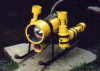
Here is the other printed gripper. Everything was printed in PLA with the exception of the pads on the fingers. I printed these out of a flexible rubber material so they would have better grip. It uses some 4-40 and 2-56 screws for assembly and a 1/8" stainless steel rod for the gripper shaft.
housingconstruction020.jpg
housingconstruction020.jpg (880.55 KiB) Viewed 44126 times
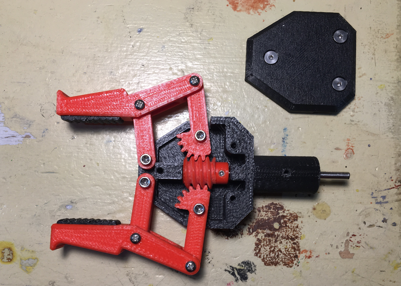
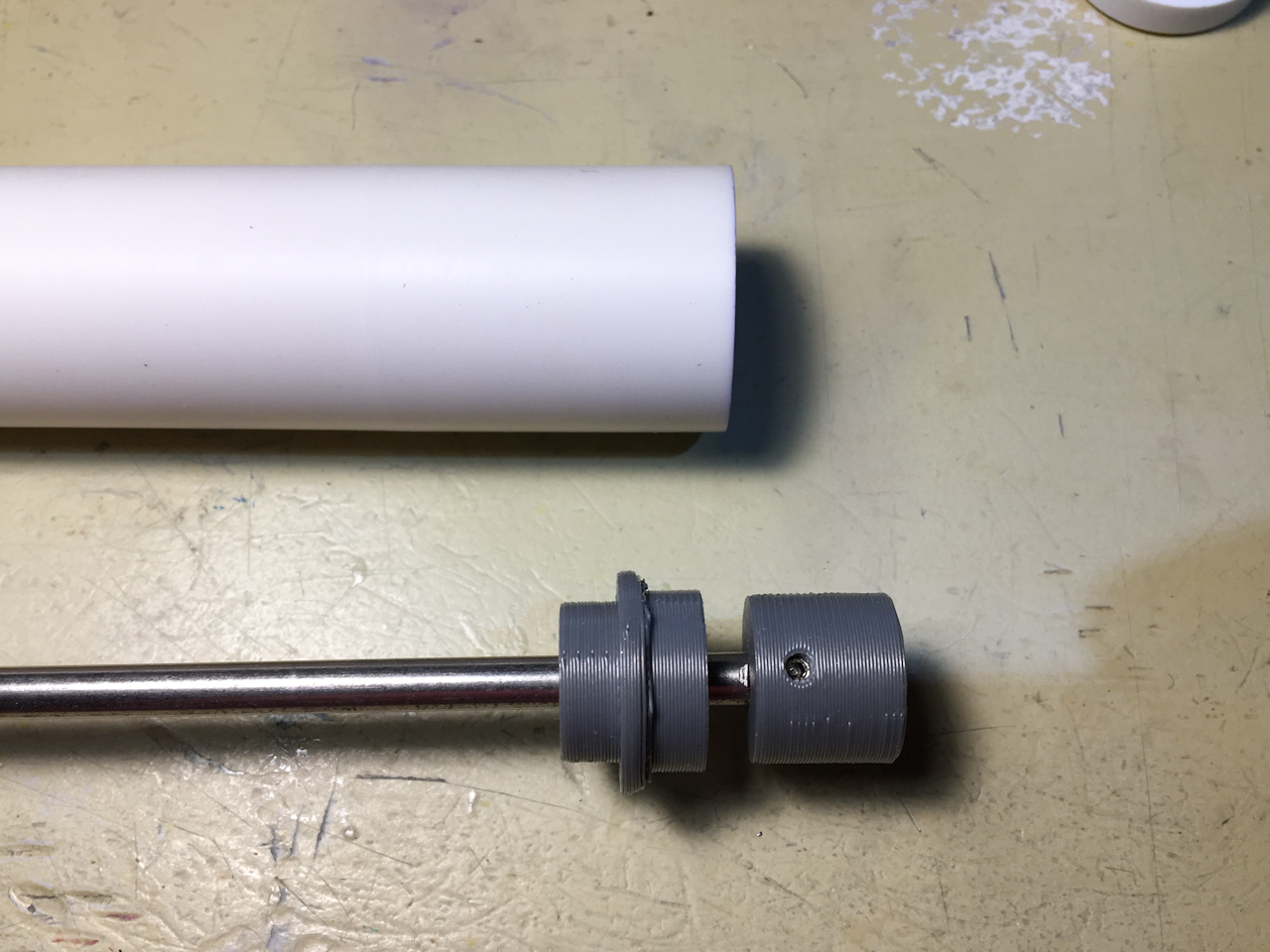
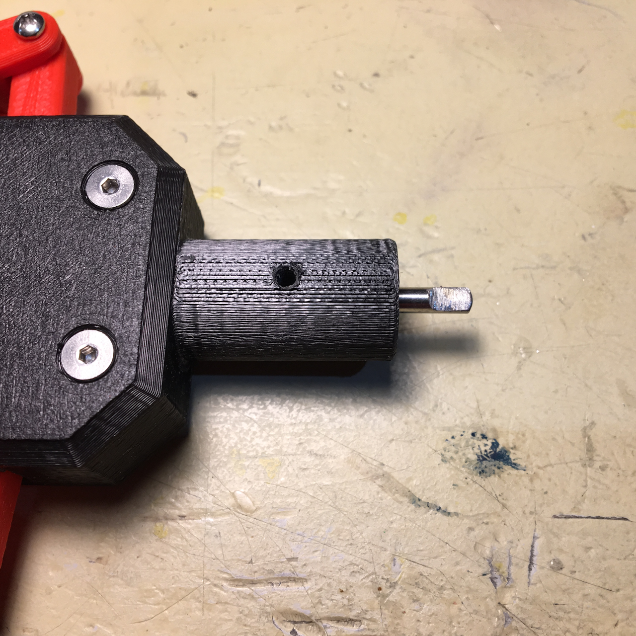
The gripper shaft has a flat spot ground in it for the 4-40 set screw on the worm gear.
housingconstruction021.jpg
housingconstruction021.jpg (863.49 KiB) Viewed 44126 times
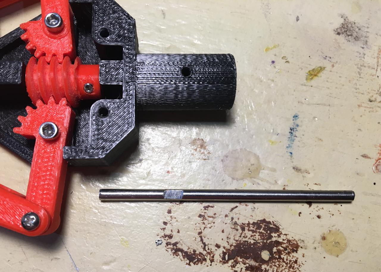
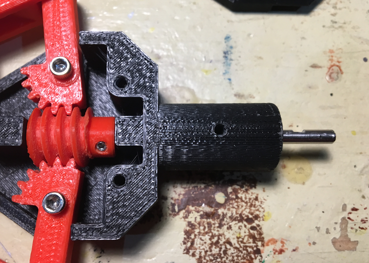
This smaller shaft of the gripper will mount to the motor shaft though a coupler. This will allow the grippers to be easily changed out when needed.
housingconstruction022.jpg
housingconstruction022.jpg (784.2 KiB) Viewed 44126 times
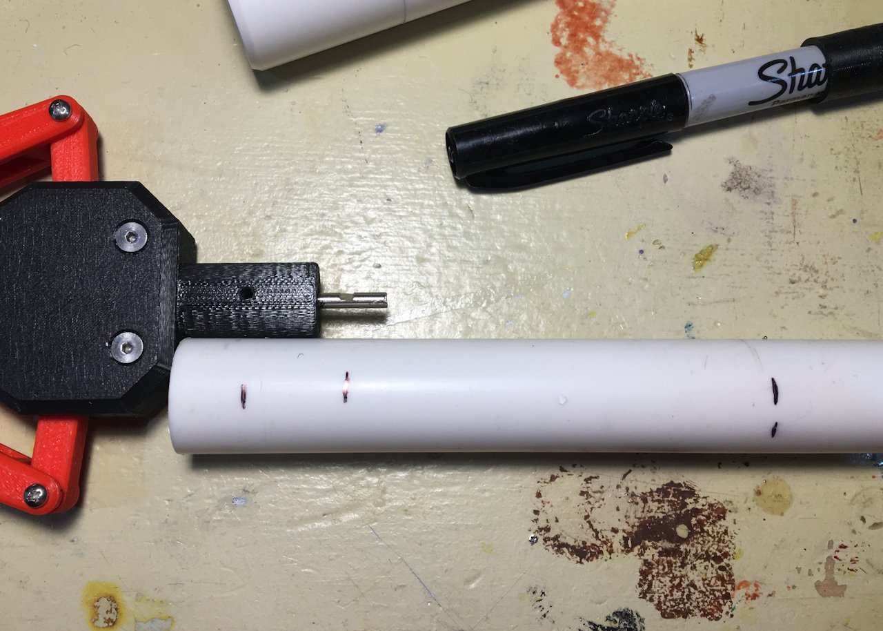
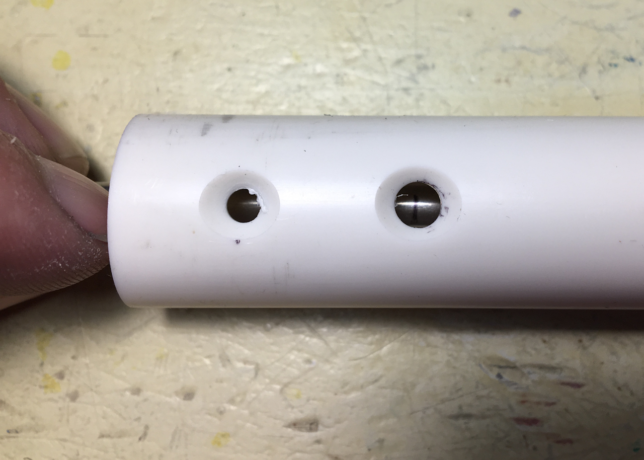
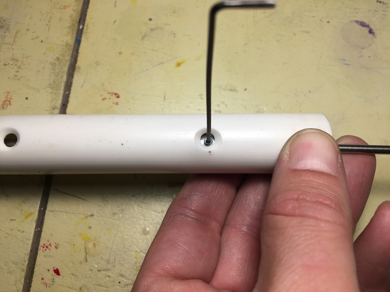
I next cut a 6" long piece of 1/2" PVC pipe to use as the arm of the manipulator. Using the gripper assembly I mark the location of the mounting holes for the gripper. The first mark is for the mounting screw and the second mark will be the access hole for the coupler set screw.
housingconstruction023.jpg
housingconstruction023.jpg (751.34 KiB) Viewed 44126 times
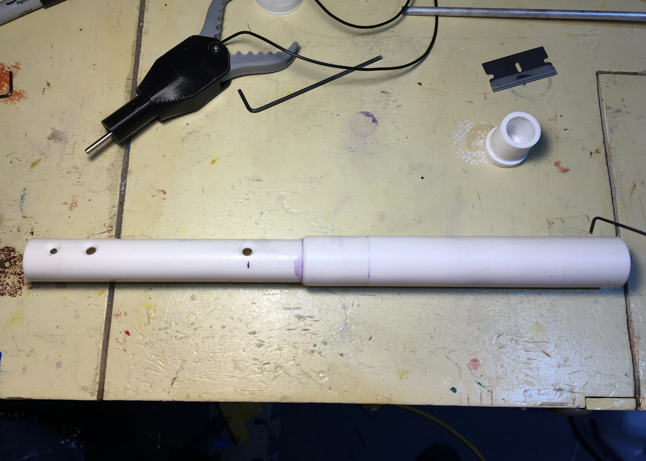
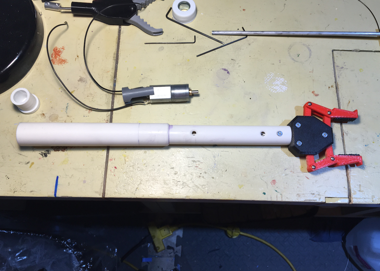
After drilling several holes through the arm on both the top and bottom the arm is glued to the motor housing portion of the manipulator. (some of the holes are for drainage because the arm portion of the manipulator is not water tight.)
housingconstruction024.jpg
housingconstruction024.jpg (797.31 KiB) Viewed 44126 times
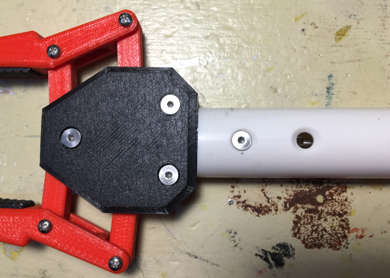
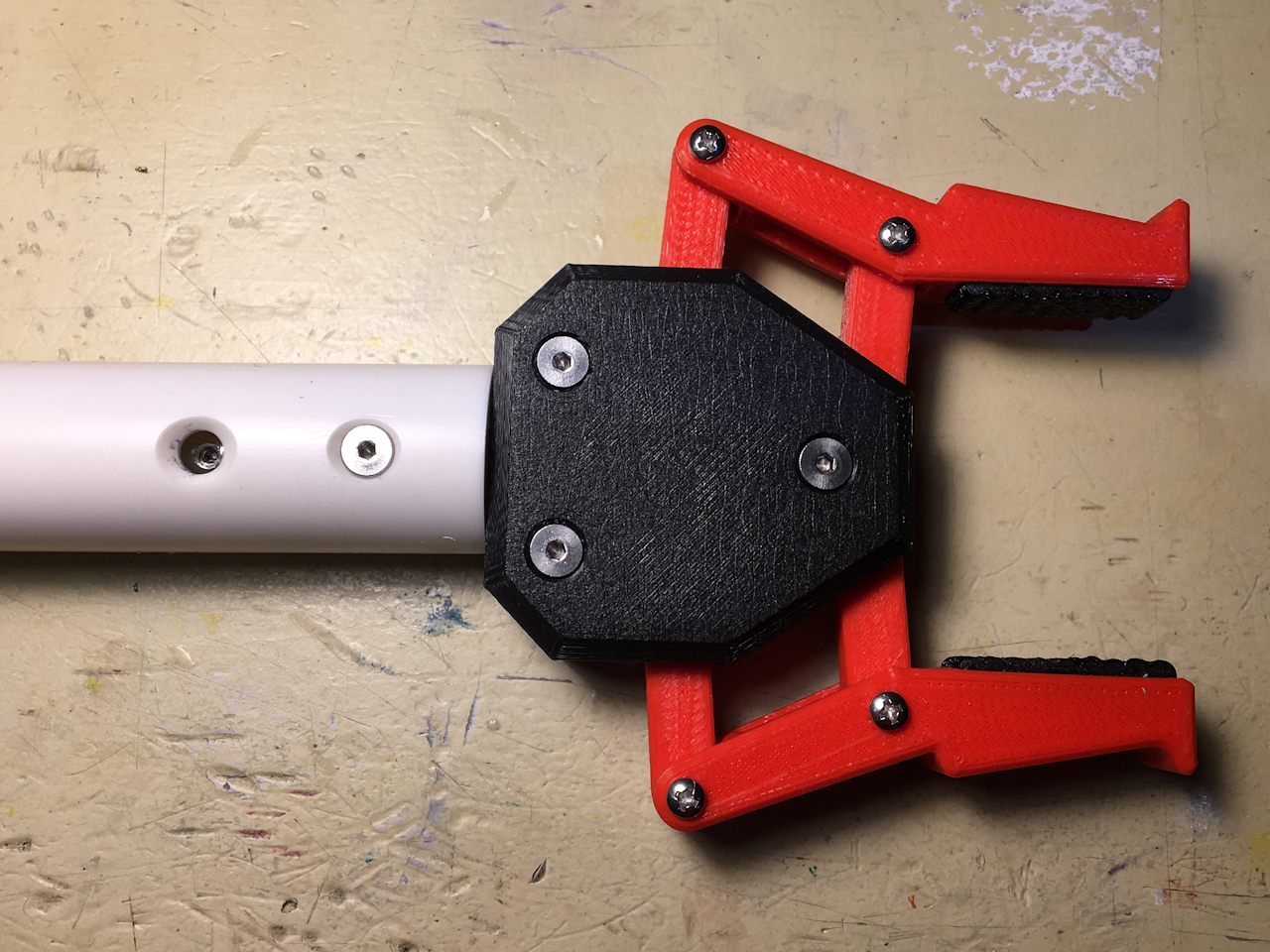
A quick test fit of the gripper is next to make sure the set screw access hole is in the correct position.
housingconstruction025.jpg
housingconstruction025.jpg (790.79 KiB) Viewed 44126 times
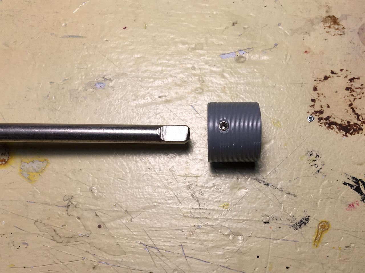
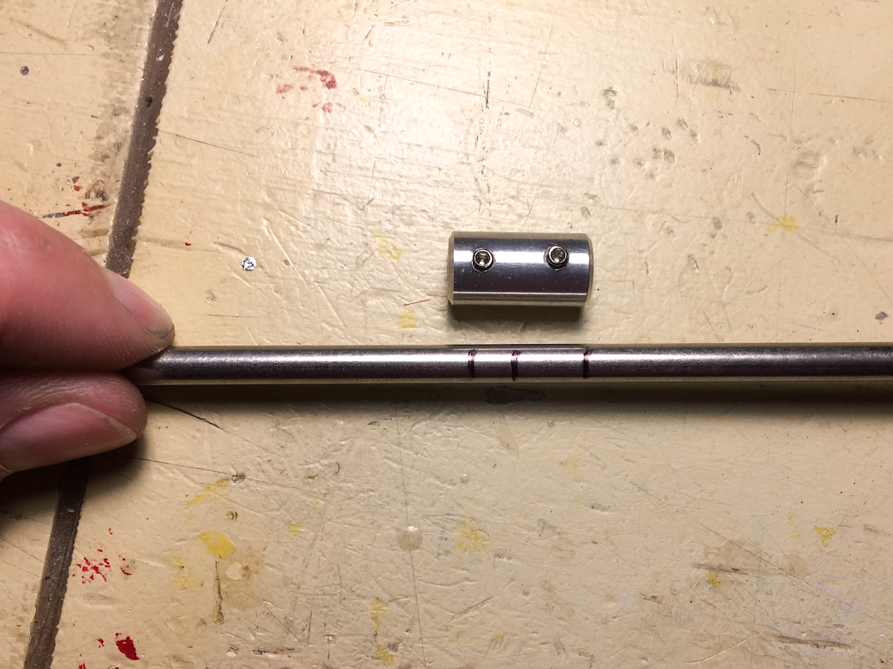
I am using a piece of 3/16" stainless steel rod for the motor shaft. Again a flat section is ground into the shaft for the shaft slip clutch coupler set screw.
housingconstruction026.jpg
housingconstruction026.jpg (659.72 KiB) Viewed 44126 times
Next the bushing is placed on the shaft and the shaft is inserted into the housing and through the seal.
housingconstruction027.jpg
housingconstruction027.jpg (554.82 KiB) Viewed 44126 times
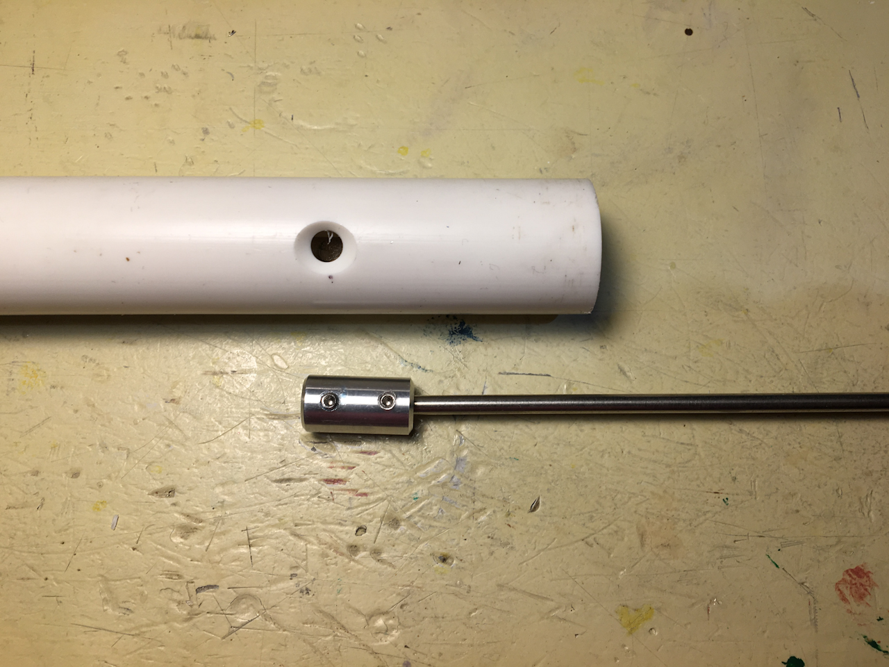
I then mark the center location of the set screw in relation to the motor shaft.
housingconstruction028.jpg
housingconstruction028.jpg (827.06 KiB) Viewed 44126 times
I made a coupler out of aluminum to join the smaller gripper shaft to the larger motor shaft. I then mark the location where the motor shaft needs to be cut as well as how far in inserts into the coupler.
housingconstruction029.jpg
housingconstruction029.jpg (722.05 KiB) Viewed 44126 times
After cutting the shaft to size and grinding another flat on that end (not shown) the shaft is reinserted into the motor housing. I temporarily attach the coupler to a scrap piece of the gripper rod so I can insert it into the arm and affix it to the motor shaft.
housingconstruction030.jpg
housingconstruction030.jpg (647.92 KiB) Viewed 44126 times
I secure the set screw in the coupler to the motor shaft through one of the holes in the bottom of the arm.
housingconstruction031.jpg
housingconstruction031.jpg (1.04 MiB) Viewed 44126 times
With the motor shaft and coupler in place I can go back and trim down the gripper shaft to length and grind the set screw flat on the end. (this is done with the shaft removed from the gripper)
housingconstruction032.jpg
housingconstruction032.jpg (824.22 KiB) Viewed 44126 times
Then is just a matter of sliding the gripper in place, securing it with a 4-40 flat head screw, and tighten the gripper shaft to the coupler.
housingconstruction033.jpg
housingconstruction033.jpg (736.35 KiB) Viewed 44126 times
Next it's on to mounting the motor. I first have to print a new motor slip clutch coupler first as this motor shaft is a different size.
User avatar
sthone
Posts: 589
Joined: Nov 8th, 2010, 9:25 pm
Location: Connecticut
Contact:

Re: Rov Reboot (3D Printed Rov)

Post by sthone »

housingconstruction034.jpg
housingconstruction034.jpg (450.17 KiB) Viewed 44081 times
Next is was on to the end cap. This is another 1/2 Plug that is turned down to fit inside the 3/4" Pipe.
housingconstruction035.jpg
housingconstruction035.jpg (758.12 KiB) Viewed 44081 times
My original idea to keep the motor from rotating was just to use a couple of pins to attach the motor mount right to the end cap so I made a template to dill some holes in the edges of the cap.
housingconstruction036.jpg
housingconstruction036.jpg (669.84 KiB) Viewed 44081 times
This Rov is not going to deep so I just use the epoxy method of sealing the through wires. (I did strip the section of the wires that will be in the epoxy to combat any leaking through the wires jacket if it gets nicked.)
housingconstruction037.jpg
housingconstruction037.jpg (739.13 KiB) Viewed 44081 times
Here the epoxy is setting up. (I finally found a use for the larger manipulator I printed years ago. :D)
housingconstruction038.jpg
housingconstruction038.jpg (560.46 KiB) Viewed 44081 times
The pin idea ended up looking a little sketchy so I ended up cutting a section out of the end cap and redesigned the mount to have a mating surface so it should be stronger now.
housingconstruction039.jpg
housingconstruction039.jpg (521.62 KiB) Viewed 44081 times
Here's how the mount and end cap go together.
housingconstruction040.jpg
housingconstruction040.jpg (564.33 KiB) Viewed 44081 times
I cut the wires just long enough to leave room for the motor to slide back and forth a bit. After soldering them on the motor its time to put this thing together.
housingconstruction041.jpg
housingconstruction041.jpg (588.19 KiB) Viewed 44081 times
Here's the scary part about this... once the end cap is glued on there is no going back. There is no fixing any problems and it's pretty much a disposable housing if anything goes wrong. (Which is why I didn't want to risk just using the small pins to keep the motor from rotating.)
housingconstruction042.jpg
housingconstruction042.jpg (481.88 KiB) Viewed 44081 times
Here is the assembled manipulator... as you can see I changed the length of the arm too. When mounted to the Rov it would have stuck out to far and I want to keep the Rov relatively small.
housingconstruction042V.GIF
housingconstruction042V.GIF (2.2 MiB) Viewed 44081 times
So far everything is working, here is a quick GIF of it in action... It's still kind if slow (I think a 60RPM motor would be better but I couldn't find one small enough.) The grip isn't the strongest either because of the slip clutch but its better than stalling the motor every time it closes to far.
housingconstruction043.jpg
housingconstruction043.jpg (815.52 KiB) Viewed 44081 times
I printed up some different fingers too with optional finger pads. The top fingers (mounted one) have round tip pads while the bottom fingers have pointy tip pads that might grip better. I still need to run some test to see what works better.
housingconstruction044.jpg
housingconstruction044.jpg (709.17 KiB) Viewed 44081 times
Here we have the golf ball grabber. This one actually has a wider opening which I could use the other fingers on if needed.

Next it's on to figure out how to mount it to the Rov. I have some different ideas for that too I want to try...
shanebou24
Posts: 3
Joined: Jan 13th, 2019, 1:40 pm

Re: Rov Reboot (3D Printed Rov)

Post by shanebou24 »

Hello Steve great work.

I was wondered what type of plastic you are using to machine your end caps.
( Im very new the the lathe world)

P.S. I was hoping as a hail Mary i would be able to use solid 3D printed end caps but after 12 iterations still no luck.
User avatar
sthone
Posts: 589
Joined: Nov 8th, 2010, 9:25 pm
Location: Connecticut
Contact:

Re: Rov Reboot (3D Printed Rov)

Post by sthone »

Thanks... The end caps on the camera tube were machined from a solid rod of PVC. This was the stuff I used https://www.mcmaster.com/catalog/125/3738 (PVC Rods 2") Any hard plastic should work though.

I tested the 3D printed parts out and yeah unfortunately even at 100% infill they will not work.

-Steve :sting:
Post Reply