Building a Magnetic Coupled Thruster.

Anything to do with Propulsion.
User avatar
sthone
Posts: 589
Joined: Nov 8th, 2010, 9:25 pm
Location: Connecticut
Contact:

Re: Building a Magnetic Coupled Thruster.

Post by sthone »

shop001.jpg
shop001.jpg (822.3 KiB) Viewed 4828 times
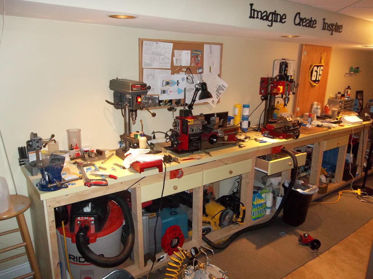
Thanks Ross that's why I still run the site after all these years... to inspire others. As far as my shop goes I'm fortunate to be setup in a basement where its always about 65 degrees all year so I no longer have to worry to much about rust. I try to keep it clean but it does get out of hand at times with so many things going at once. Above is my current setup (I should update my shop thread one of these days I guess) as usual bench top space is hard to find :) I have a new toy coming this week :D so I might have to clean a bit more to make some more room. Anyway back to the fun stuff....
mdhousing076.jpg
mdhousing076.jpg (792.54 KiB) Viewed 4828 times
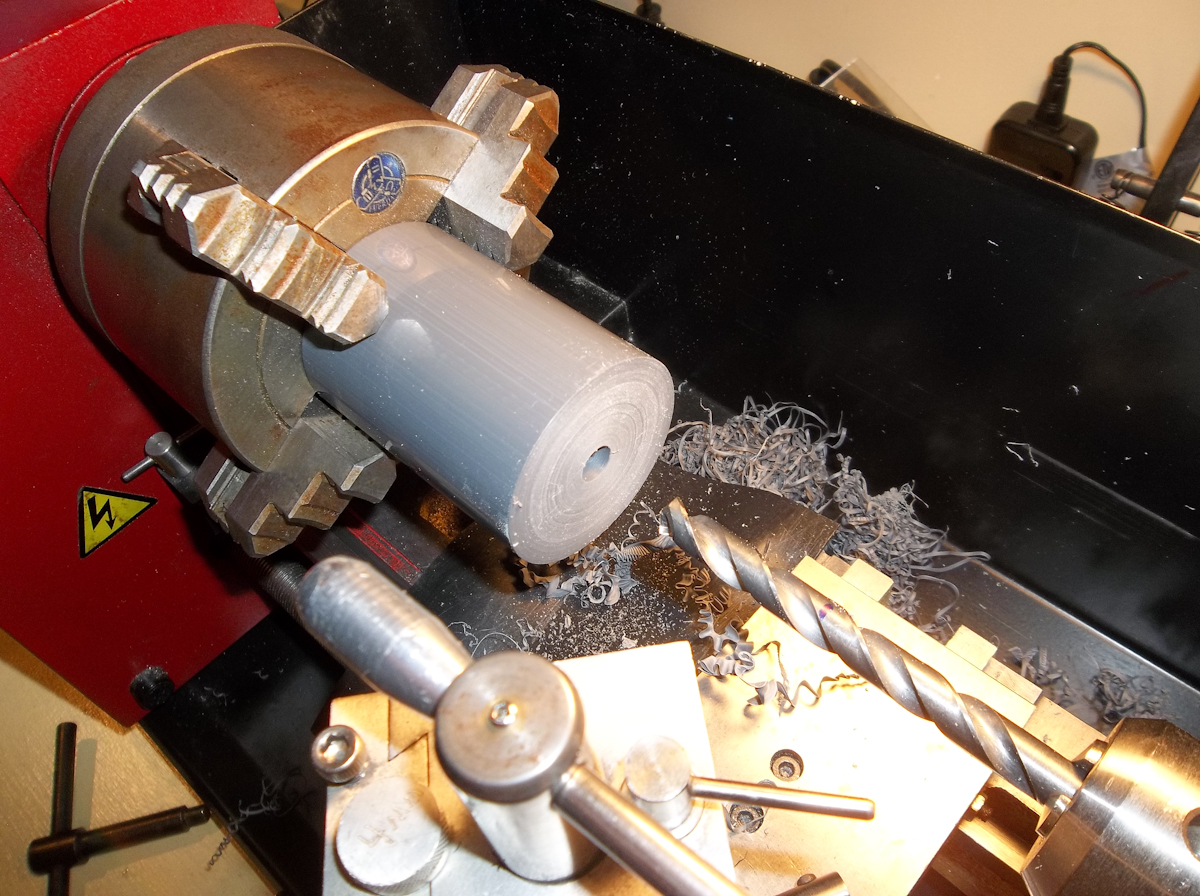
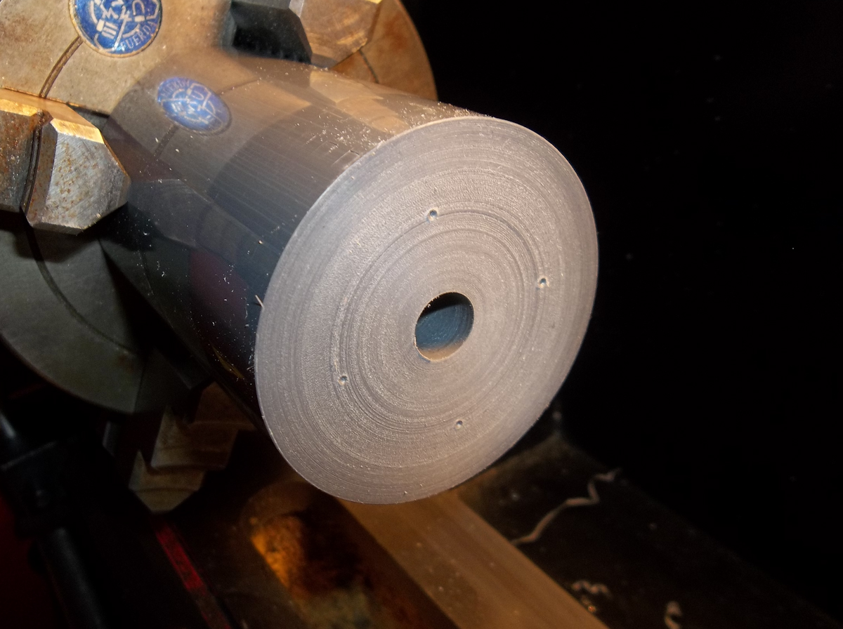
Onto the prop rotor. I start with another chuck of PVC, face it and drill a 23/64" hole in the end.
mdhousing077.jpg
mdhousing077.jpg (753.5 KiB) Viewed 4828 times
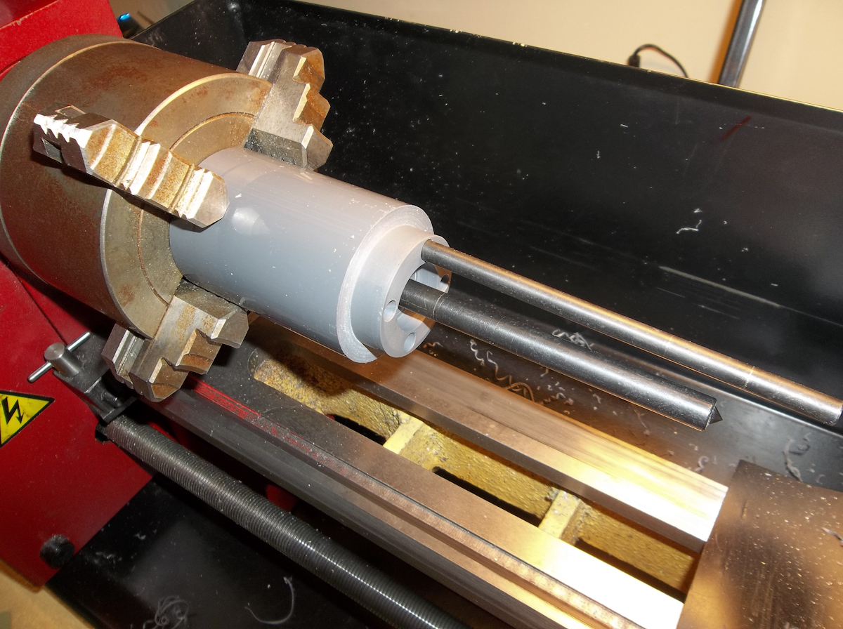
Using a 23/64" Transfer punch to center the other rotor I transfer the magnet locations using a 1/4" punch. (I later noticed the rotor is backwards from what it should be but the holes should still be close enough for the prototype.)
mdhousing078.jpg
mdhousing078.jpg (520.2 KiB) Viewed 4828 times
Now that I have my magnet locations I can start boring the piece out to mate with the cap.
mdhousing079.jpg
mdhousing079.jpg (502.5 KiB) Viewed 4828 times
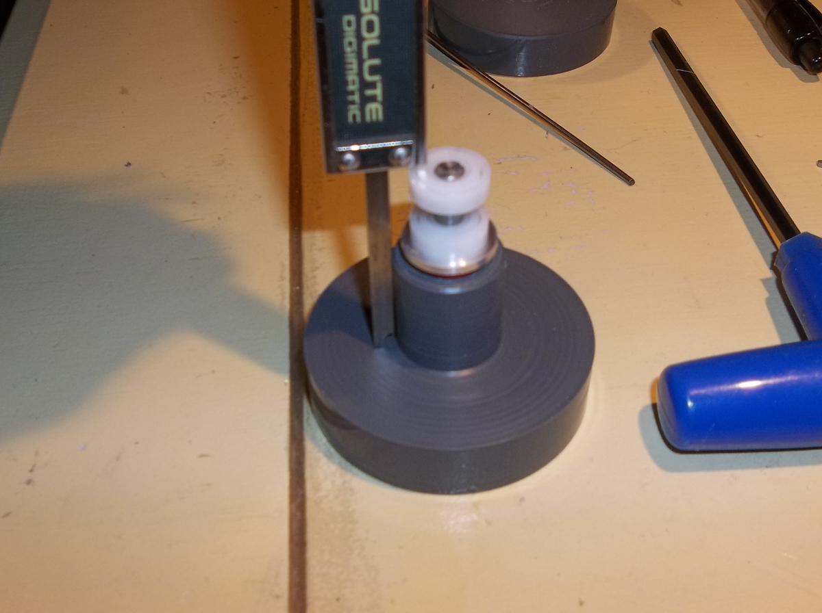
I start by measuring the depth needed for the bearings.
mdhousing080.jpg
mdhousing080.jpg (673.37 KiB) Viewed 4828 times
I first drilled a 31/64" hole and then bored that out to .50" to a depth of 1.45" to fit both bearings.
mdhousing081.jpg
mdhousing081.jpg (572.61 KiB) Viewed 4828 times
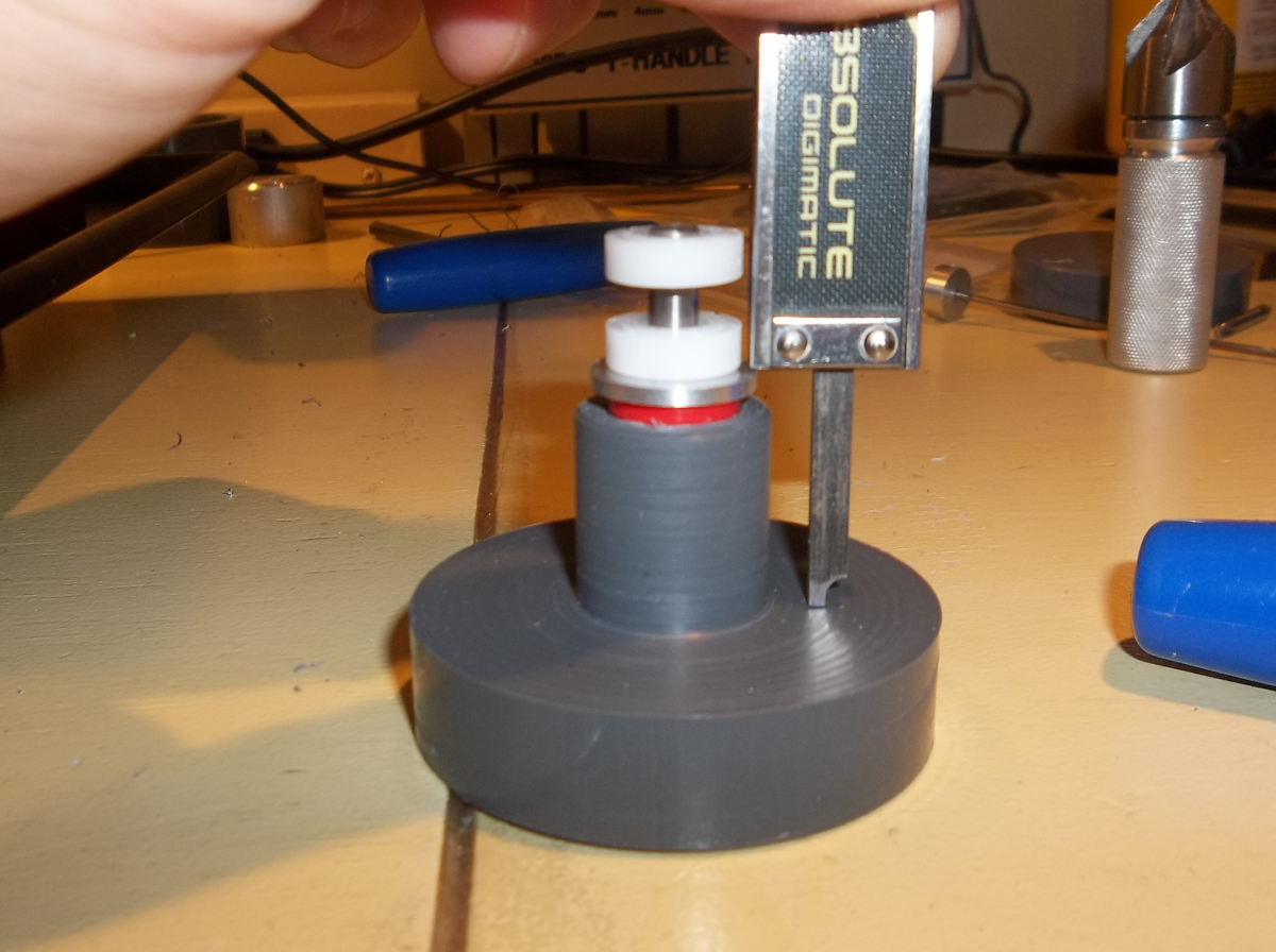
Next I measure for the new thrust bearing washer I made. (I didn't show making this)
mdhousing082.jpg
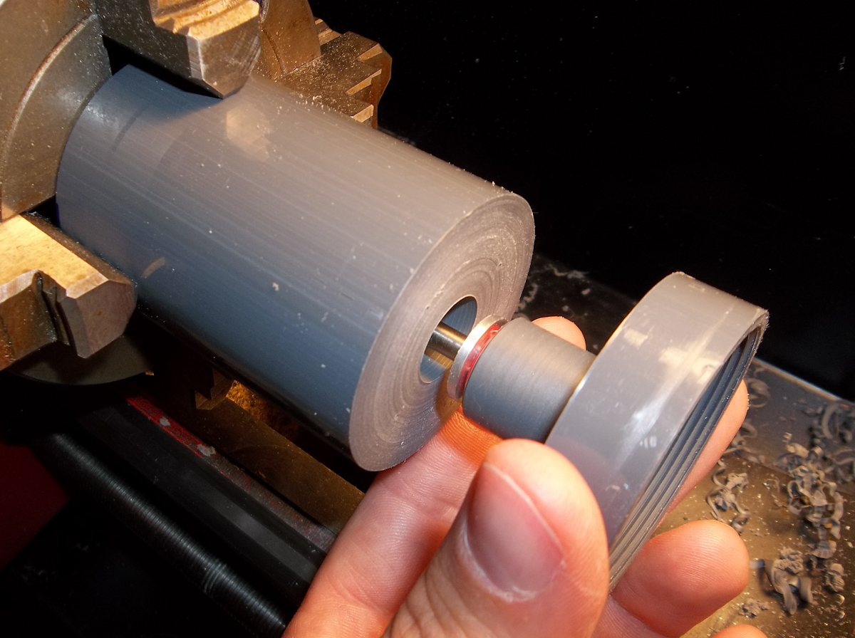
mdhousing082.jpg (597.51 KiB) Viewed 4828 times
Then I bored out .620" to a depth of .890"
mdhousing083.jpg
mdhousing083.jpg (461.36 KiB) Viewed 4828 times
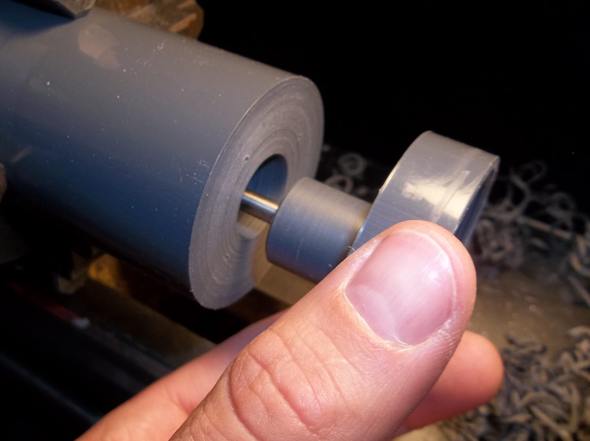
Next I bored out to clear the step on the cap.
mdhousing084.jpg
mdhousing084.jpg (697.9 KiB) Viewed 4828 times
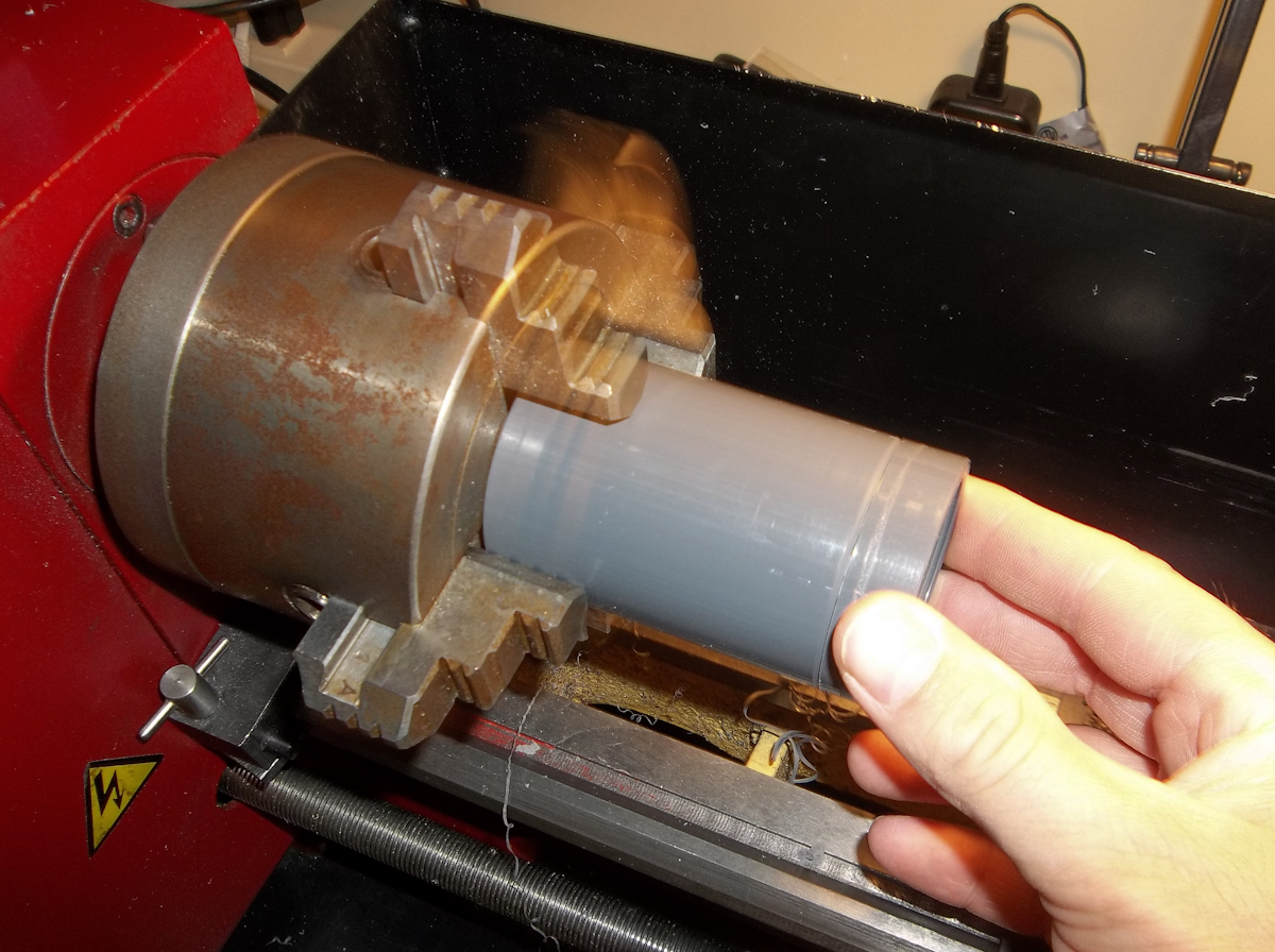
I tested out the thrust bearing by spinning the piece in the lathe and just holding the cap against it. It seemed to work well at this stage.
mdhousing085.jpg
mdhousing085.jpg (618.29 KiB) Viewed 4828 times
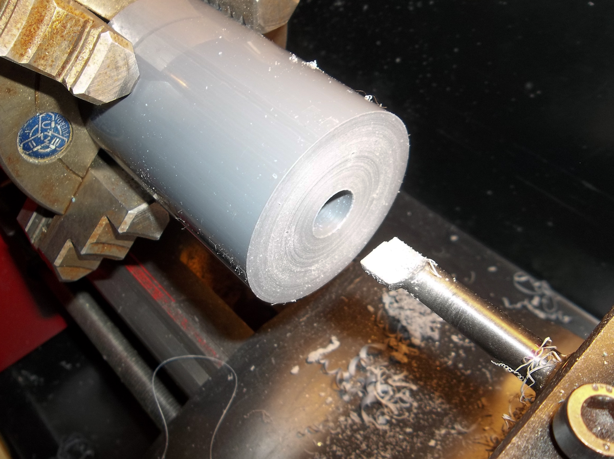
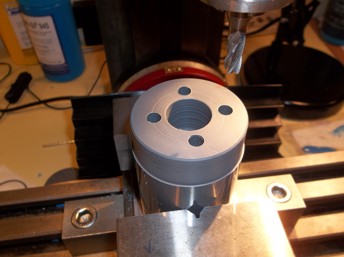
Next I transferred the workpiece over to the lathe and plunged cut the magnet holes.
mdhousing086.jpg
mdhousing086.jpg (536.93 KiB) Viewed 4828 times
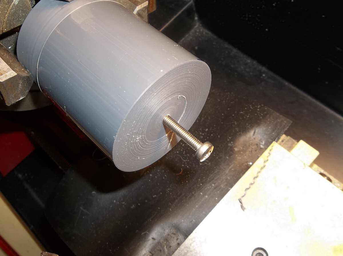
After that it was back over to the lathe to drill and tap for the 4mm screw for the prop.
mdhousing087.jpg
mdhousing087.jpg (613.39 KiB) Viewed 4828 times
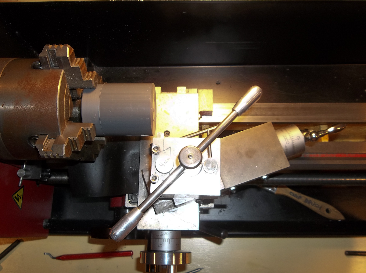
Next I had to setup the angle on the compound slide to turn the cone shape.
mdhousing088.jpg
mdhousing088.jpg (672.29 KiB) Viewed 4828 times
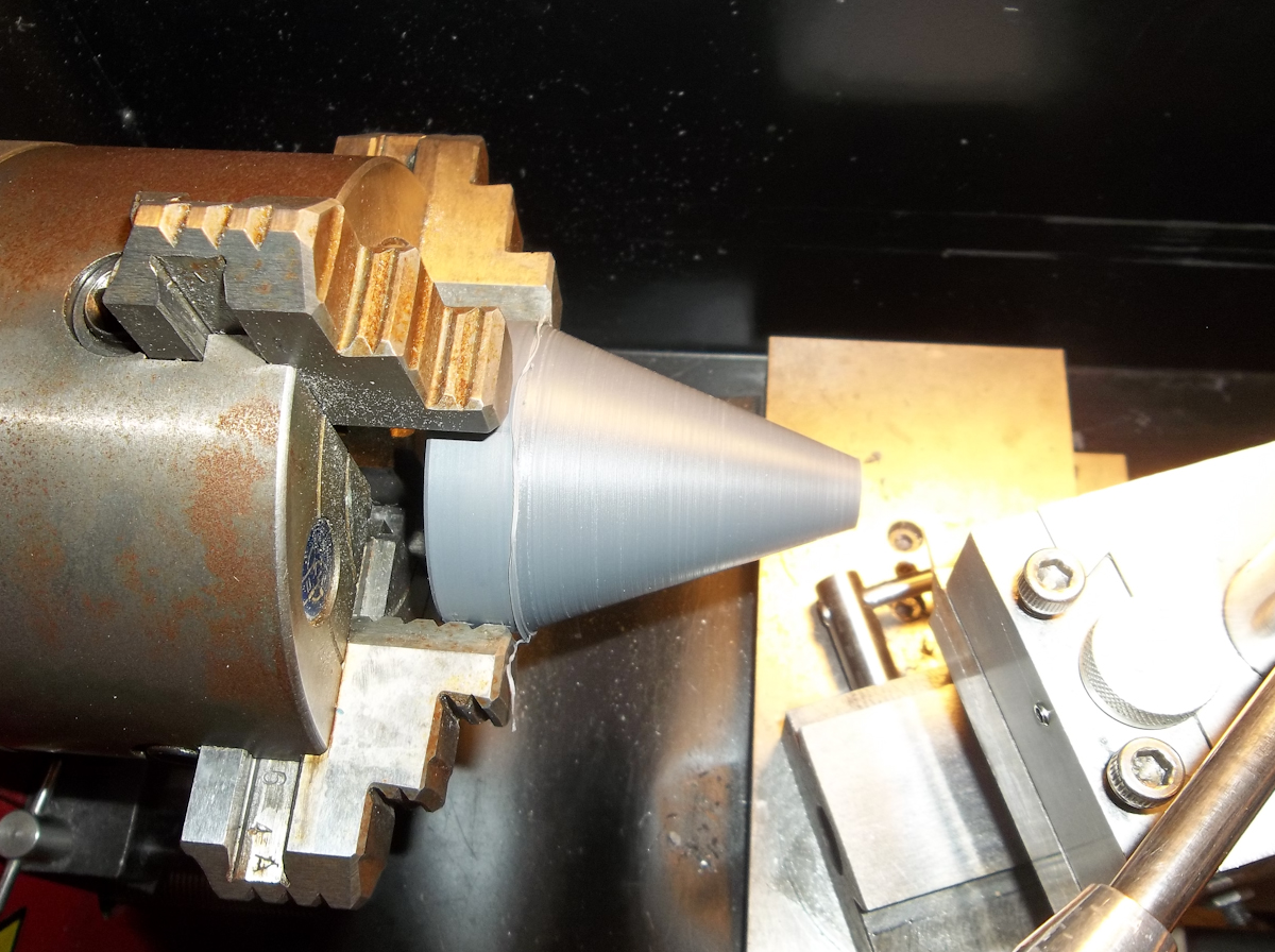
After a bunch of cutting this is how it looks. I was off a bit with my measurements so I'll have to clean the step up at the end later on.
mdhousing089.jpg
mdhousing089.jpg (699.91 KiB) Viewed 4828 times
I quick test fit reveals it's a tad bit wobbly but it spins very freely. Next I have to glue the magnets in and go from there.

-Steve :sting:
User avatar
sthone
Posts: 589
Joined: Nov 8th, 2010, 9:25 pm
Location: Connecticut
Contact:

Re: Building a Magnetic Coupled Thruster.

Post by sthone »

After a little hiatus I'm back at it........
mdhousing-090.jpg
mdhousing-090.jpg (121.73 KiB) Viewed 4735 times
...at this point I've glued in the magnets and after a few quick spin up tests everything seems like its working pretty good so far. It's a tad bit wobbly but better than I expected. Next it's on to the end cap.
mdhousing091.jpg
mdhousing091.jpg (104.67 KiB) Viewed 4735 times
I first face off the back of the end cap and knock off the corner a bit to reduce the sharp edge.
mdhousing092.jpg
mdhousing092.jpg (104.96 KiB) Viewed 4735 times
Flipping the piece in the chuck I start a hole with an endmill so I can fit my boring bar in there.
mdhousing093.jpg
mdhousing093.jpg (120.21 KiB) Viewed 4735 times
I then bored out a section to almost the end of the cap to make room for the motors wires. I left the end cap a little longer than I needed because this is my last piece of material and if a screw up the threads I can just cut them off and try again without having to order more stock and redo the entire cap.
mdhousing094.jpg
mdhousing094.jpg (130.84 KiB) Viewed 4735 times
Next I measure my major diameter of the threads on the housing....
mdhousing095.jpg
mdhousing095.jpg (131.38 KiB) Viewed 4735 times
....after subtracting for the depth of the threads I finish boring out the cap to around 1.73".
mdhousing096.jpg
mdhousing096.jpg (98.27 KiB) Viewed 4735 times
Using my internal threading bit I give the cap its threads and hope for the best.
mdhousing097.jpg
mdhousing097.jpg (115.18 KiB) Viewed 4735 times
A quick test fit and it seems I actually measure right.
mdhousing098.jpg
mdhousing098.jpg (90.03 KiB) Viewed 4735 times
Here is the almost finished end cap next to the housing.
mdhousing099.jpg
mdhousing099.jpg (95.08 KiB) Viewed 4735 times
At this point the thruster is pretty much complete with the exception of the exits for the motor wires.

To be continued.....

-Steve :sting:
kendelrio
Posts: 11
Joined: Oct 22nd, 2013, 9:37 am
Location: Alexandria, La

Re: Building a Magnetic Coupled Thruster.

Post by kendelrio »

Outstanding jorb! When (if) I ever get around to building my own, I may go with this setup.


Quick question: What depth is your housing rated to? You could go much deeper if you have your thruster in an oil filled housing. We use a dialectric oil on our motors with a positive compensation system (very easy to build, I may post a thread on it when I get a minute to write it up) and can dive up to 15,000 feet with no implosion worries.

Let me know if there is any interest in it please.

Again, great job! I wish I had your shop at home!
User avatar
sthone
Posts: 589
Joined: Nov 8th, 2010, 9:25 pm
Location: Connecticut
Contact:

Re: Building a Magnetic Coupled Thruster.

Post by sthone »

Ken, my housing hasn't been rated, this is more or less just a prototype to see if the concept works.
mdhousing100.jpg
mdhousing100.jpg (90.02 KiB) Viewed 4727 times
Next it is on to the through hull connectors. I start with a piece of .25" brass and turn the front down to .20"
mdhousing101.jpg
mdhousing101.jpg (80.55 KiB) Viewed 4727 times
After that using a 12-24 die I thread the piece.
mdhousing102.jpg
mdhousing102.jpg (96.85 KiB) Viewed 4727 times
Then a .1406 hole gets drilled in the end. These are where the motors connectors will plug in.
mdhousing103.jpg
mdhousing103.jpg (93.01 KiB) Viewed 4727 times
Using the parting tool the piece is then cut off.
mdhousing104.jpg
mdhousing104.jpg (90.58 KiB) Viewed 4727 times
The piece is then rechucked in the lathe and I turn down a small step and then drill a .1094" hole in the end. The power wires will connect here and the step is for a bit of heat shrink tubing.
mdhousing105.jpg
mdhousing105.jpg (88.5 KiB) Viewed 4727 times
Here are the three finished connectors and a quick test to make sure the motor plug fits securely.
mdhousing106.jpg
mdhousing106.jpg (101.78 KiB) Viewed 4727 times
After that I drill and trap three holes in the end cap for the connectors.
mdhousing107.jpg
mdhousing107.jpg (70.84 KiB) Viewed 4727 times
The connectors get a bit of Teflon tape and are started by hand.
mdhousing108.jpg
mdhousing108.jpg (139.35 KiB) Viewed 4727 times
Next I protect the connector with a piece of soda can and I tighten them with a pair of pliers.
mdhousing109.jpg
mdhousing109.jpg (73.22 KiB) Viewed 4727 times
So far everything is working out as I had planned.
mdhousing110.jpg
mdhousing110.jpg (79.69 KiB) Viewed 4727 times
Next I soldered the wires right to the connectors. I was going to use a screw on fitting here but to speed things up I went this route for now. (I was a little worried that the heat from soldering would melt the housing but I was quick about it so I think its fine.
mdhousing111.jpg
mdhousing111.jpg (71.52 KiB) Viewed 4727 times
After the wires were connected I added a little heat shrink tubing just to pretty it up. (I'm not really worried about water proofing the connections.)
mdhousing112.jpg
mdhousing112.jpg (109.8 KiB) Viewed 4727 times
Before screwing on the cap I had to pre-twist the motor wires in the opposite direction so when screwing on the actual cap the wires don't twist up and pull free.
mdhousing113.jpg
mdhousing113.jpg (87.62 KiB) Viewed 4727 times
I originally planed on using o-rings to seal the housing but for now I just use more Teflon tape on the threads. (at this point I'm not really concerned about it leaking)
mdhousing114.jpg
mdhousing114.jpg (102.47 KiB) Viewed 4727 times
Well here it is all ready get wet and start some testing.

-Steve :sting:
User avatar
olegodo
Posts: 222
Joined: Aug 30th, 2013, 9:47 am
Location: Bergen, Norway

Re: Building a Magnetic Coupled Thruster.

Post by olegodo »

Really nice work! Looking forward to seeing test results
User avatar
sthone
Posts: 589
Joined: Nov 8th, 2010, 9:25 pm
Location: Connecticut
Contact:

Re: Building a Magnetic Coupled Thruster.

Post by sthone »

I got this in the test tub today and while it kind of worked it needs some tweaking. It spins right up but before it can reach full throttle the magnets break away from each other. I might try adjusting the gap and see if that helps but it might just need more magnets. I didn't bother testing the thrust or amps draw because I only was trying to see if the coupler worked. Anyway I'm going to try the gap adjustment first and then go from there.....

-Steve :sting:
a_shorething
Posts: 289
Joined: Sep 10th, 2013, 5:26 pm
Location: New Jersey Shore

Re: Building a Magnetic Coupled Thruster.

Post by a_shorething »

Hi Steve,

Great to see you're back in testing mode.

You might be able to do something with your programming if the change is too abrupt for the magnets to keep up with. Maybe have it set up so that it ramps up instead of going from 0-100% as fast as the input is sent. I know ideally it would be 'locked' together, but it could act as a kind of clutch if you do it right. That would also protect the motor if the prop got stuck on something.

Just a thought.
User avatar
sthone
Posts: 589
Joined: Nov 8th, 2010, 9:25 pm
Location: Connecticut
Contact:

Re: Building a Magnetic Coupled Thruster.

Post by sthone »

I think its more just breaking loose because of the drag of the prop at higher speeds. Even if I increase the throttle as slowly as I can it still breaks away before hitting top rpm. The whole protecting the motor aspect encase of a tangling is exactly what I'm going for though. That's why I designed the motor mount to be adjustable so I could dial in the break away force to allow for such things. Hopeful once I add a few magnets it will be strong enough so I can get to that point.

-Steve :sting:
a_shorething
Posts: 289
Joined: Sep 10th, 2013, 5:26 pm
Location: New Jersey Shore

Re: Building a Magnetic Coupled Thruster.

Post by a_shorething »

Very cool, good luck. Looking forward to more progress.

I'm getting back into testing my mag coupler too (finally). Will post in another thread.
Post Reply