Building a Magnetic Coupled Thruster.
Re: Building a Magnetic Coupled Thruster.
Thanks Bubbles that's I good idea I will look into that option as I go.
Next it is onto the motor mount. I cut another chuck of PVC and again after centering it in the lathe it is faced. Next I actually have to measure (no TLAR here) what will be the minor diameter of the threads for the mount. It's about 1.465" as you can see. Knowing the thread depth of 18TPI is about .07" I had to turn down the work piece to 1.535 for the major diameter before I can start the threading process. Next using the external threading tool again I thread the piece to match the housing. I quick test fit to make sure everything is correct before I remove the work piece from the lathe. Next I measure the original mount to determine the correct drill size (25/64") to use to match the center hole... and drill the corresponding hole in the center of the piece. This will only be used to mark the mounting holes in the new mount. Next it was over to the mill to cut a relief channel for the motor wires. Then using a 25/64" transfer punch to center the mount onto the work piece I use another punch to mark the center of each mounting hole. I then mount the piece in the mill and using a center pointer I line up the first hole. Next I use a center drill to start the hole. This will keep the drill bit from walking and also put a bevel on the hole face for the screw. After that I used a 1/8" bit for the through hole. I think the screws are actually metric so this will give me a little play when mounting the motor. I then repeat this process for the other three holes. I also drill two 3/16" holes in the mount, these will be used to screw it into the housing and later adjust the motor spacing. One last trip back over to the lathe and I use a parting tool to cut off the mount from the work piece. Here is the mount so far, it still needs a little clean up but its complete for the most part. I'm using a pair of needle nose pliers to test fit the mount in the housing, I will probably make a tool for this later on. I need to buy some longer screws before I can mount the motor.
Re: Building a Magnetic Coupled Thruster.
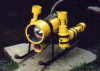
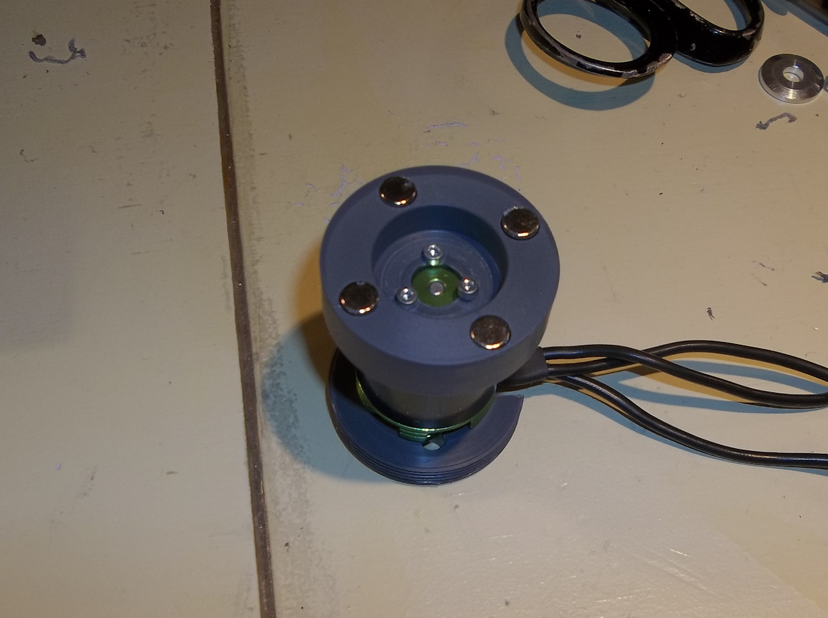
So I bought some longer screws and now have the motor secured to the mount, next its on to the internal rotor.
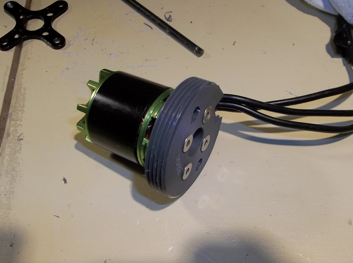
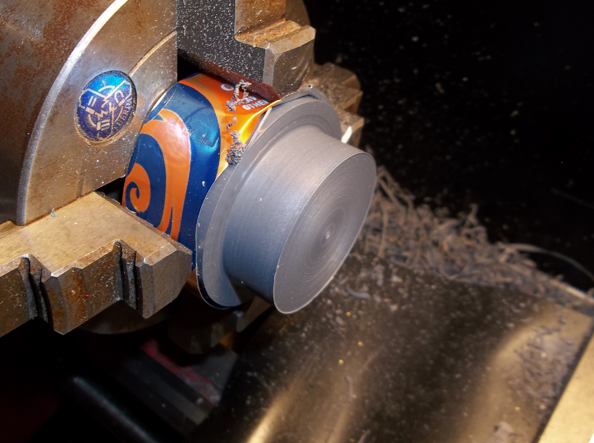
I haven't bored out the front of the housing yet so I use the back (minus the internal threads to measure for the rotor diameter. The rotor will end up being about 1.53".
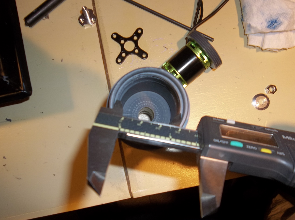
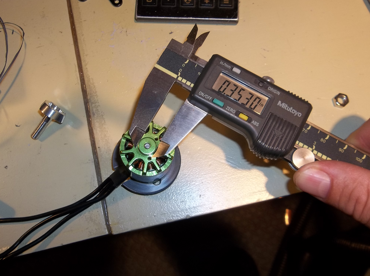
After measuring my magnets I come up with a measurement of .45" for the thickness of the rotor and mark that on my workpiece.
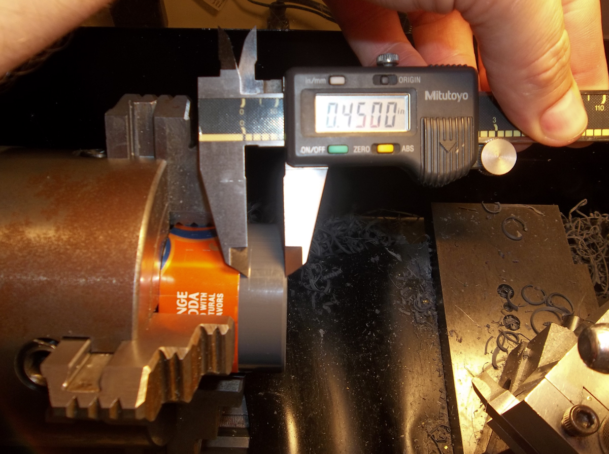
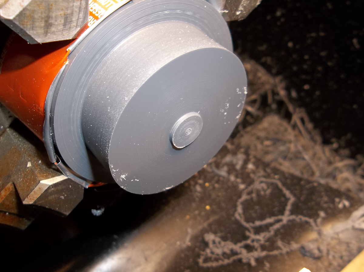
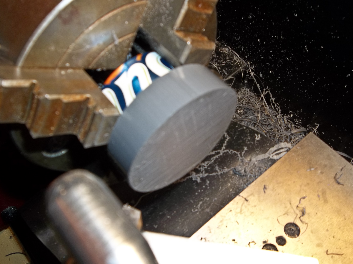
Here I have turned down the piece for the correct diameter and depth.
I then had to measure the front step of the motor where the stock propeller adapter would mount.
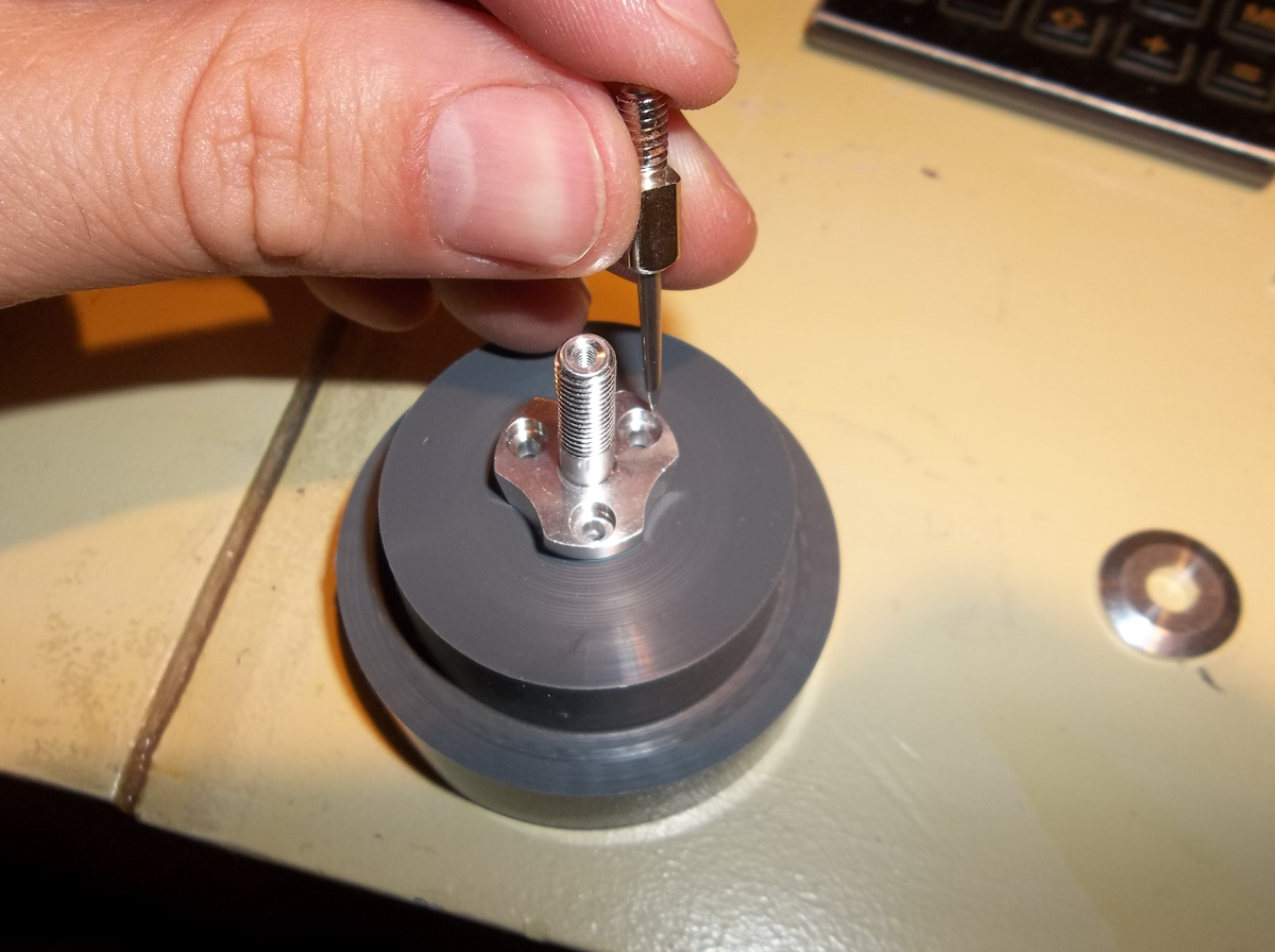
I turn down the front of the workpiece to duplicate that little step. (This will center the adapter while I mark the mounting holes.)
I don't have a transfer punch small enough for these holes so I use a little pointy thing to mark the holes as best I can.
I have to turn the piece around and face the other end so it sits flat in the mill for the next step. (I should have done this to the workpiece at the start but I forgot.)
Next it was over to the mill and once again using my center pointer I align the piece for the holes.
I used a 5/64" drill bit to drill through for the screws. My holes look a little off which is the result of not having the right transfer punch. (remember kids always use the right tool for the right job)
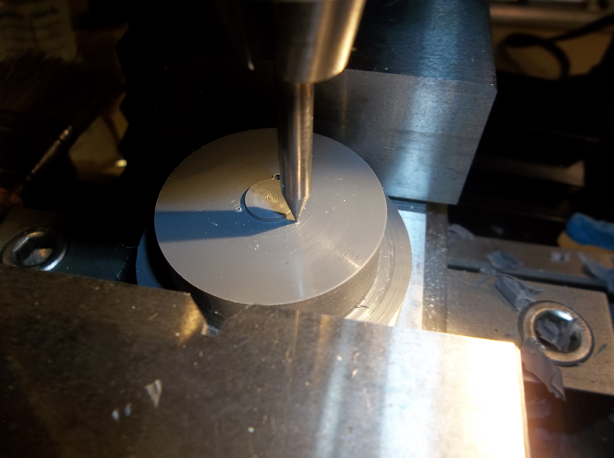
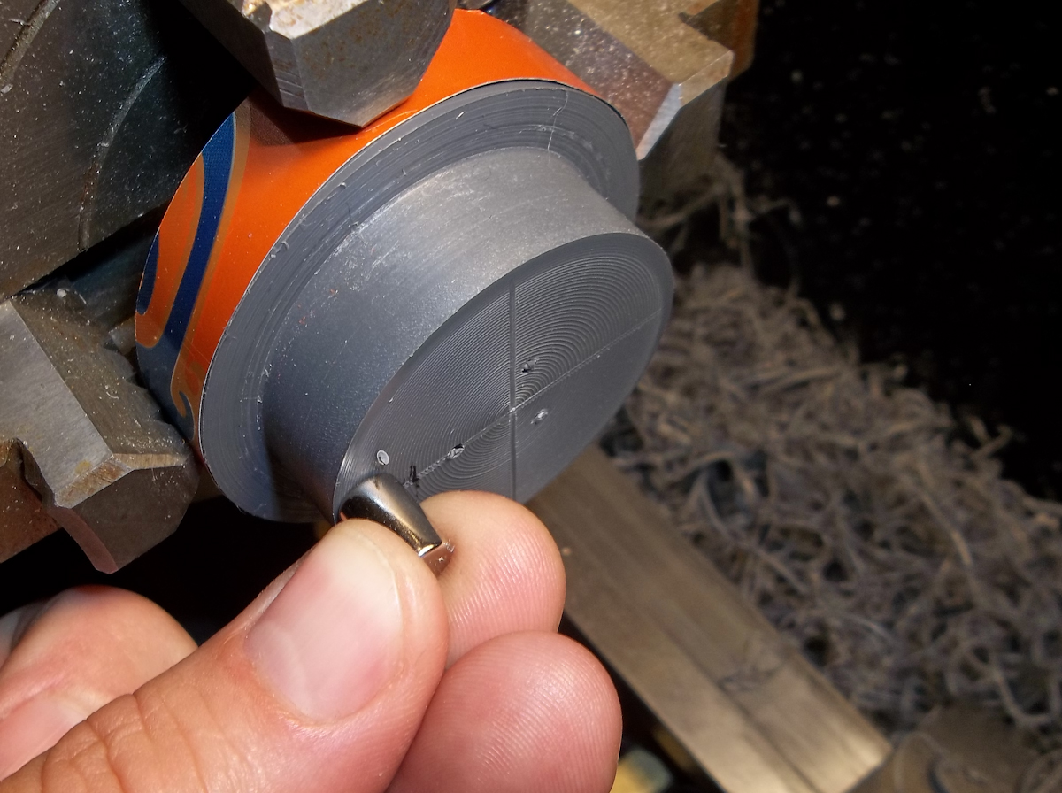
Next I motor the piece back in the lathe and clean off the little step I made before. Then using the cross slide I drag the tool across the face making a line, then rotate the chuck 90 degrees and do it again. These marks will be for the placement of the magnets.
After that I roughly mark how much of the inter rotor I can remove. This will lighten the rotor a bit and allow me to use the stock mounting bolts.
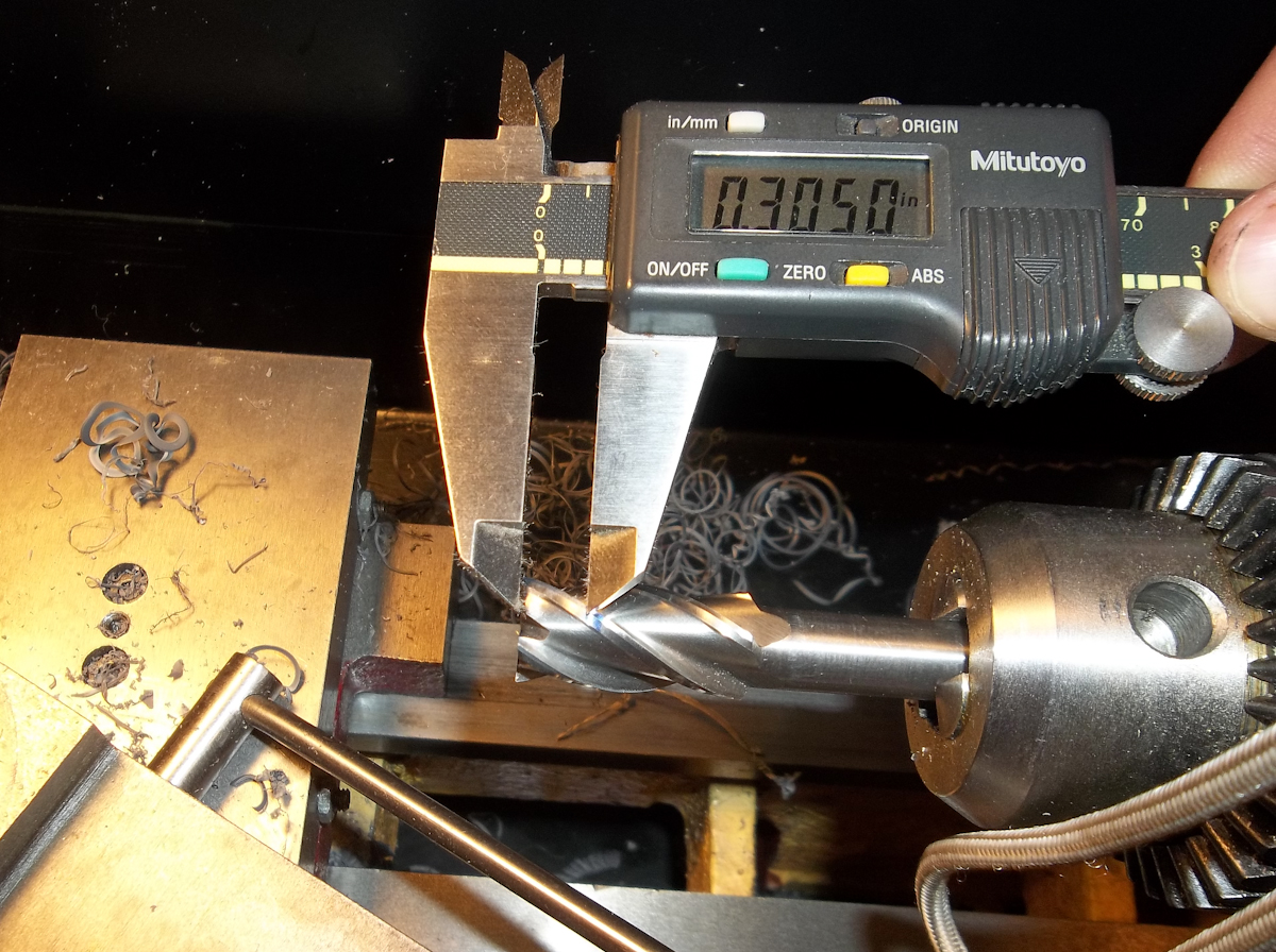
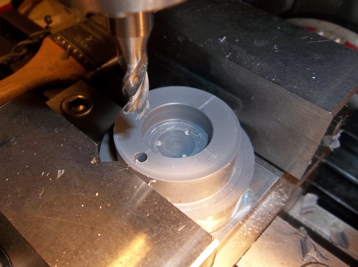
After measuring my screw length and knowing my rotor will be about .45" thick I calculate that I need to bore out center of the rotor to about a depth of about .305". I am starting the hole with a plunge cut using a 1/2" end mill so I roughly mark the depth on the end mill with a marker. (being this is only a prototype I'm back to the TLAR method for most non critical things.)
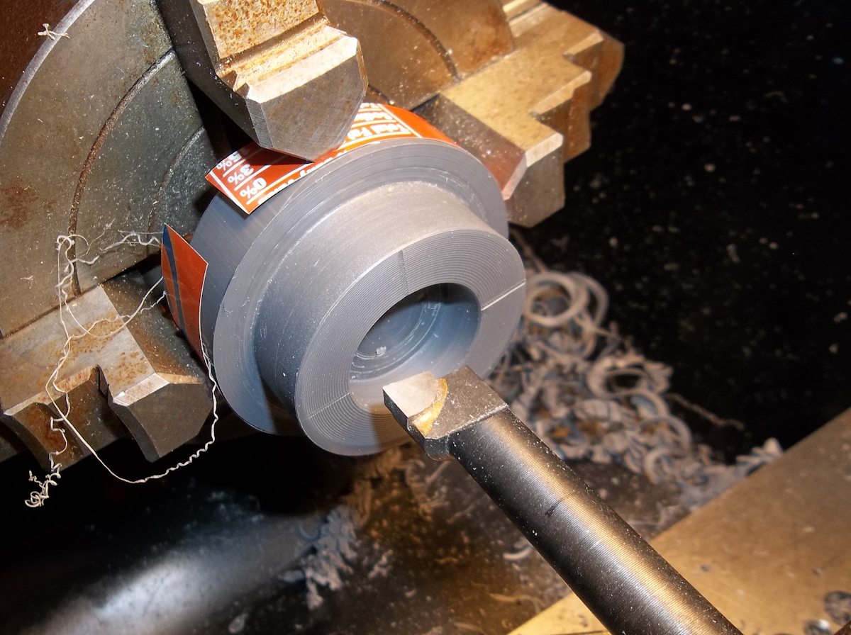
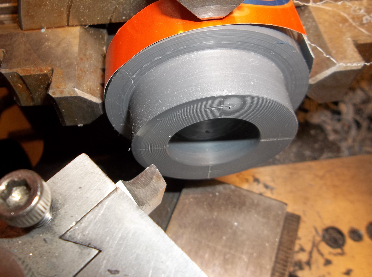
Using my boring bar I then finish out removing excess material from the center of the rotor.
After that I measure whats left with my calipers (not shown) divide by by half and the using my tool bit again mark the center point for each magnet.
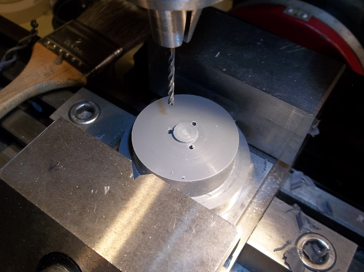
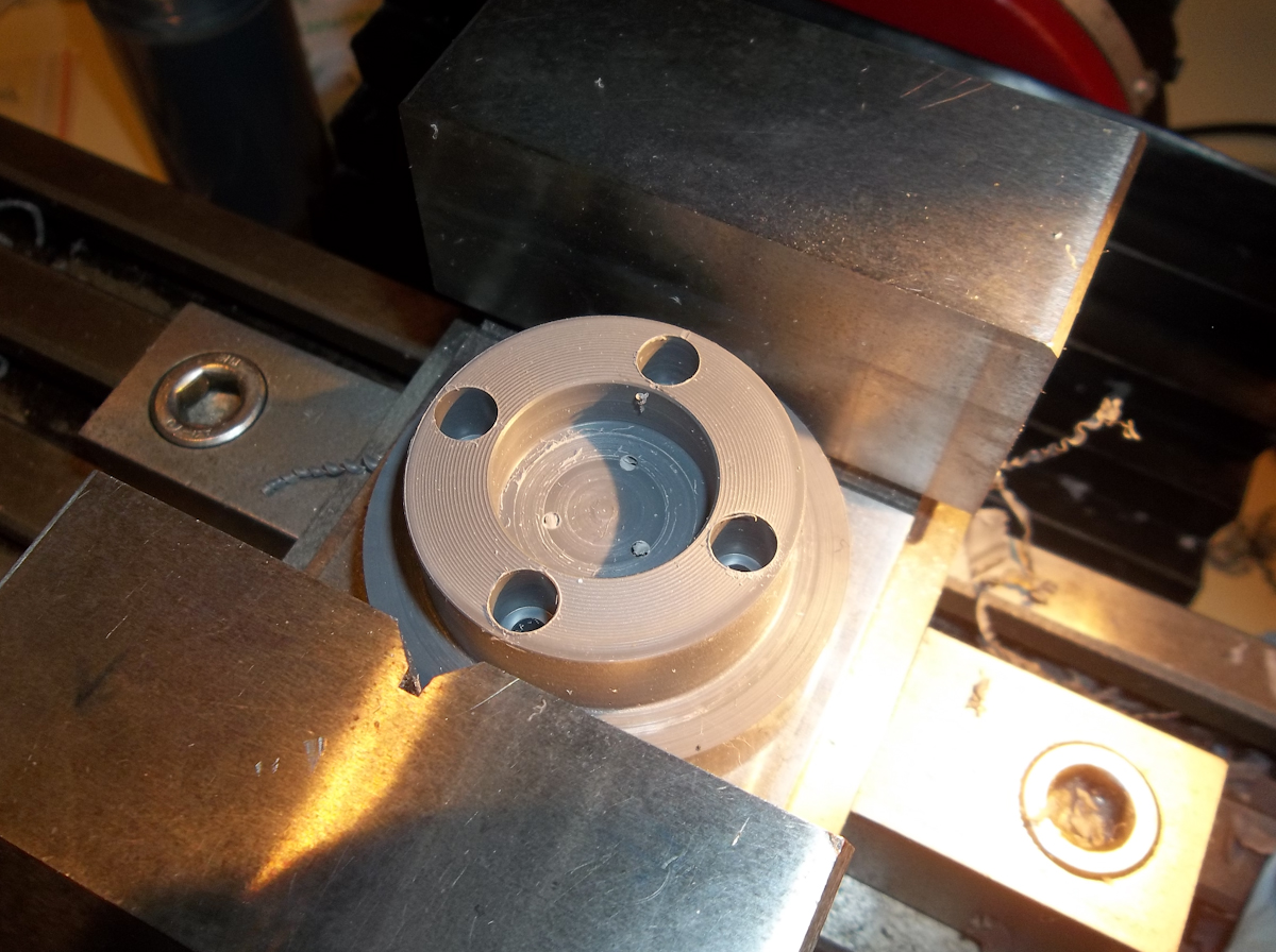
Back over to the mill I center each hole as before and drill through first with a 5/32" drill bit (these holes will be used to transfer the magnet holes to the outer rotor later on.) I then finish the holes for the magnets with a 1/4" end mill so they have a flat bottom.
Here the holes for the magnets have all be drilled. I'll probably have to clean them up a bit because I wasn't as critical with the depths as I should have been.
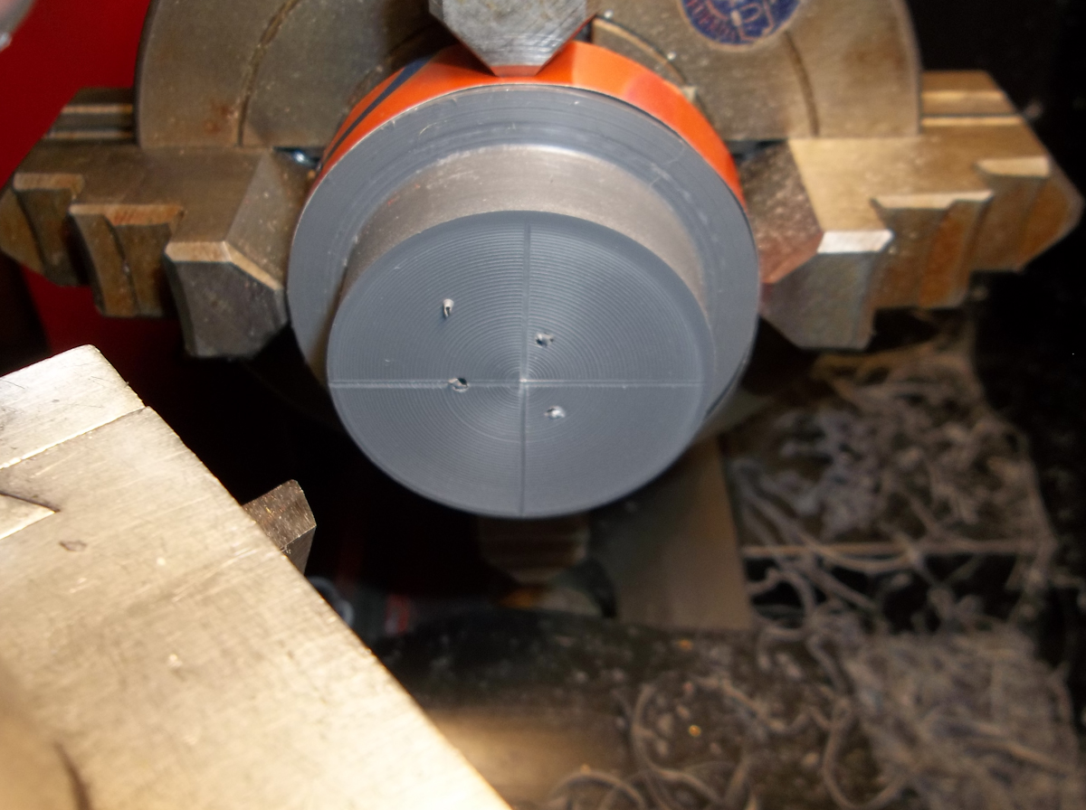
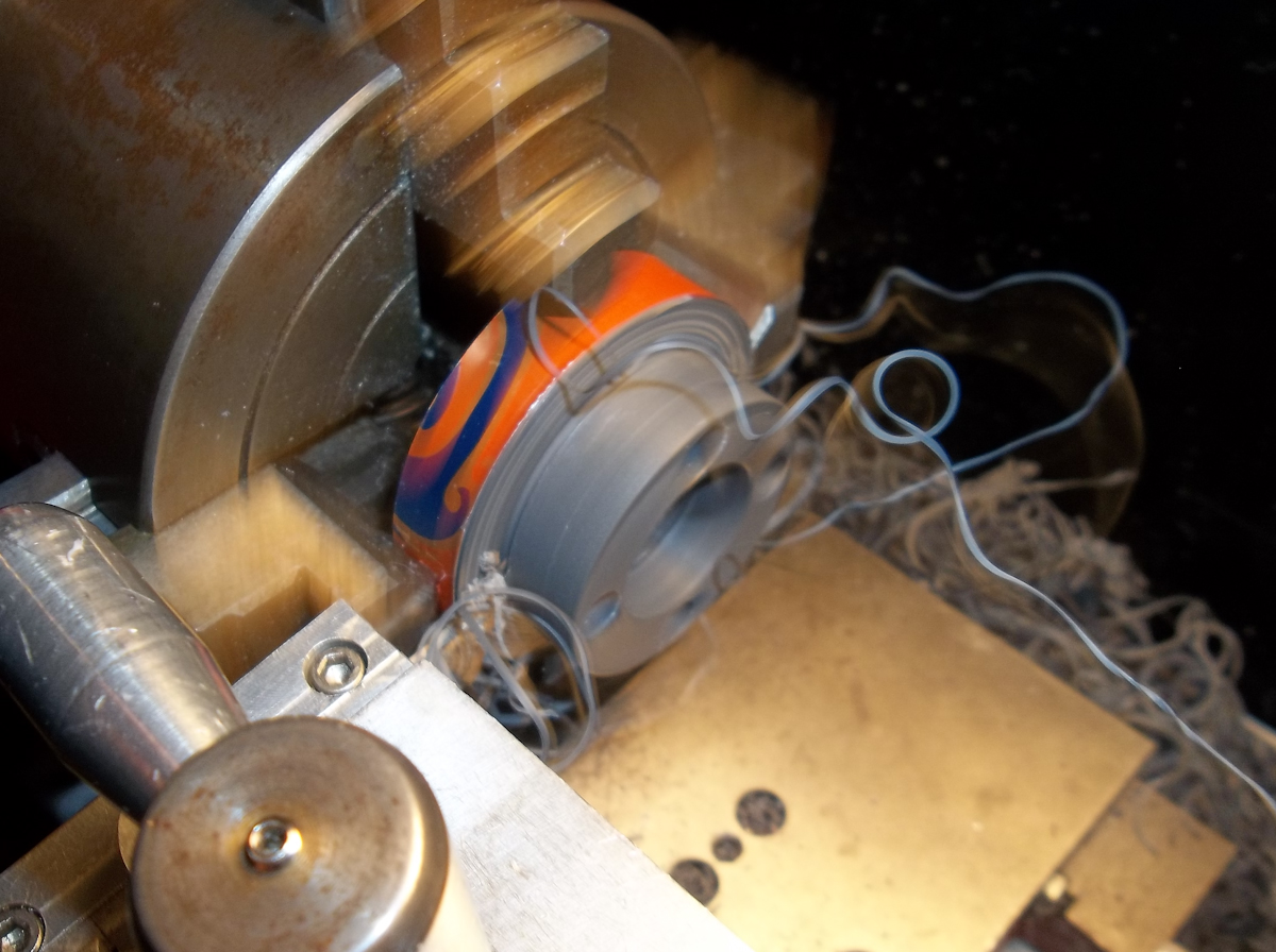
A quick trip back to the lathe to cut off the rotor with a part off tool.
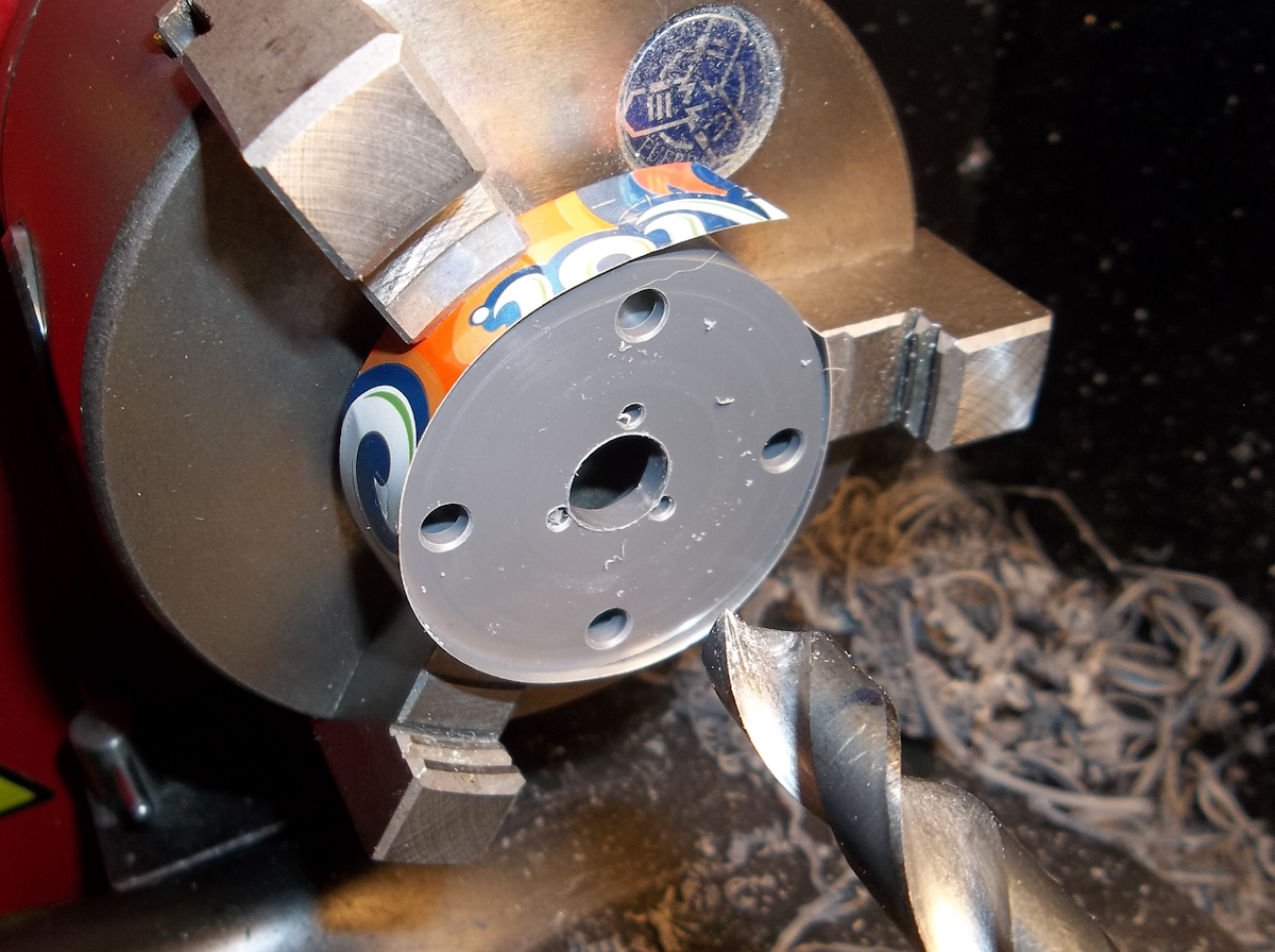
Next the piece is rechucked and I drill a 23/64" hole for the step on the motor.
and here we have the finished rotor mounted to the motor. I still have to glue in the magnets and give it a spin up to see how balanced it is.
Re: Building a Magnetic Coupled Thruster.
The next step was to bore out the front of the housing just wide enough to fit the rotor.
A quick test fit to make sure there is enough clearance for it to spin without any interference.
I then screwed the motor half way into the threads (to allow for adjustment either way) and I measure the depth that I need to trim the housing.
With the piece back into the lathe I once again use the part tool to trim off the excess piece of the housing. The housing came out much shorted than I originally intended but this was all because I couldn't cut the internal threads as deep into the housing as I wanted to.
After I had the housing trimmed down to size I turned the end down and threaded it for the rotor cap.
Another quick test fit of the motor and rotor and then it's on to making the rotor cap.
Re: Building a Magnetic Coupled Thruster.
The suspense is killing me, it's like watching a movie that keeps stopping LOL. This is great work, I look forward to your next post (every time)
Re: Building a Magnetic Coupled Thruster.
Sorry TwoBeaner, to be continued once again..............
Re: Building a Magnetic Coupled Thruster.
That's okay, good work takes time. Thomas Edison said "The thing I lose patience with the most is the clock. Its hands move too fast"sthone wrote:Sorry TwoBeaner, to be continued once again..............
Take all the time you need and keep up the good work, its inspiring/motivating to the rest of us.
Re: Building a Magnetic Coupled Thruster.
Next I drilled and tapped the cap to 8/32" to fit the shaft.
I aslo cut a recess for the thrust bearing washer.
For the shaft I turned down a piece of 3/16" stainless steel rod to .164" to match the 8/32" threads I cut in the cap.
The treads of the shaft are being cut with a die by hand. I use the end of the drill chuck to keep the die holder straight while I start the threads.
To cut the threads I hold the Die holder and just spin the chuck by hand.
Here is the completed shaft.
I quick test fit of the bearings shows me I'm going to need a bigger outside washer on the thrust bearing, the way it is now the rotor would rest against the top bearing and shaft and the thrust bearing wouldn't be doing much. I'll have to turn down a larger washer so the rotor rest against that point and then the thrust bearing will take that load as the magents will pull the rotor toward the housing.
Re: Building a Magnetic Coupled Thruster.
Keep up the good work, looks awesome!
Re: Building a Magnetic Coupled Thruster.
Hi Steve, I think what you have posted is a great how-to pictorial that de-mystifies lathe work and could inspire some folks to acquire one. For ROV parts, my own lathe is often used for modifying PVC plumbing bits and the like. Very familiar looking environment, even the PVC stock looks the same, though workshop much cleaner and less rusty than mine, and those numbers on the caliper are different
Ross
Ross
Re: Building a Magnetic Coupled Thruster.
Oh how I long for the metric system here. I use calipers everyday and I still have to use a calculator to go from fraction to decimal sometimesrossrov wrote:and those numbers on the caliper are different