I have been working on my code recently, and I am ready to post an update.
Here is my current set up:
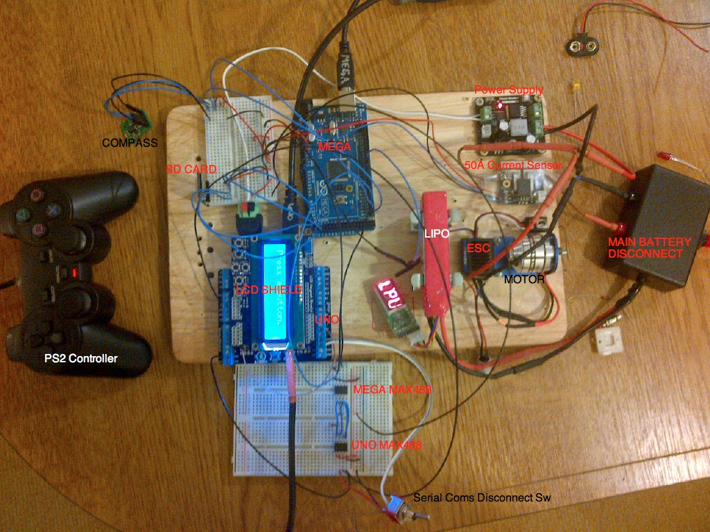
- Current Control Setup
- ROV Layout2.jpg (327.83 KiB) Viewed 17008 times
Arduino Uno (Surface Module)
1- PS2 Controller
1-
LCD Shield
1-
MAX488 IC
1- SPDT switch
1-
Power Supply
Arduino MEGA2560 (ROV Control)
1-
Micro SD Module
1-
50 Curent Sensor
1-
MAX488 IC
1- Turnigy 18A ESC (no longer listed on Hobby King. Hope it is replaced soon!)
1- 11.1V 3S1P 1300mA LiPo Battery
1- Disconnect switch for LiPo Battery
1- Tilt Compensated Compass (no code in program yet...)
UNO CODE
Code: Select all
/*
Code by: KR2_DIVING (Ryan)

          )    O
         (   o . O
          )   () .
          /  O   o
       _.|._ o .()                    ***********************
      / _:_ \                         *****             *****
     |.(_ _).|                        *****     UNO     *****
     _\. : ./_                        *****   SURFACE   *****
    / |..:..| \                       *****             *****
   /_/ `---' \_\                      ***********************
   \_)        \_)
     \   T   /
     _)__|__(_
    /....|....\
    """"" """""
  ---KR2_DIVING---

I don't mind if you use this code for your own use.  I have made it freely available online.
However, please be sure to credit my work, and the work of Bill Porter when using or passing
this code on.

Please direct any questions to: kr 2 diving (at) gmail (dot) com

Version  History     Mega
Version  Date        Match  Notes
-------  ----------  -----  -----
  1.0    2013-04-08  v1.0   File changed from ROV_CONTROL_V1_9b to ROV_UNO_V1_0
*/


//Libraries written by Bill Porter.
#include <PS2X_lib.h>        // Library for interfacing with PS2 Controller.
#include <EasyTransfer.h>    // Library to simplify serial communication.

#include <LiquidCrystal.h>   // Include LiquidCrystal library

/*----------------------------------------------------------------------------------------------
----------                  VARIABLE DECLALARATIONS                                   ----------
----------------------------------------------------------------------------------------------*/

/****************************************************
***** Playstation controller related variables  *****
****************************************************/

PS2X ps2x;             // create PS2 Controller Class

int LY = 0;            // Variable for fixed values based on Left Stick Y-axis
int LX = 0;            // Variable for fixed values based on Left Stick X-axis
int RY = 0;            // Variable for fixed values based on Right Stick Y-axis
int RX = 0;            // Variable for fixed values based on Right Stick X-axis

int R1state = 0;       // used to determine state of R1 button
int R2state = 0;       // used to determine state of R2 button
int L1state = 0;       // used to determine state of L1 button
int L2state = 0;       // used to determine state of L2 button


int error = 0;           // used by PS2X.lib
byte type = 0;           // used by PS2X.lib
byte vibrate = 0;        // used by PS2X.lib

/*
right now, the PS2X library does NOT support hot pluggable controllers, meaning
you must always either restart your Arduino after you conect the controller,
or call config_gamepad(pins) again after connecting the controller.
---> Add code to call config_gamepad(pins) incase of disconnect during operation. On push button?
*/

/****************************************************
*****      LiquidCrystal related variables      *****
****************************************************/

LiquidCrystal lcd( 8, 9, 4, 5, 6, 7 );
int keyPress;          // analog value used to detemine which key is pressed on the LCD sheild

#define BUTTON_ADC_PIN     A0  // A0 is the button ADC input
#define LCD_BACKLIGHT_PIN  10  // D10 controls LCD backlight
// ADC readings expected for the 5 buttons on the ADC input
#define RIGHT_10BIT_ADC           0  // right
#define UP_10BIT_ADC            120  // up
#define DOWN_10BIT_ADC          280  // down
#define LEFT_10BIT_ADC          480  // left
#define SELECT_10BIT_ADC        720  // right
#define BUTTONHYSTERESIS         30  // hysteresis for valid button sensing window
//return values for ReadButtons()
#define BUTTON_NONE               0  //
#define BUTTON_RIGHT              1  //
#define BUTTON_UP                 2  //
#define BUTTON_DOWN               3  //
#define BUTTON_LEFT               4  //
#define BUTTON_SELECT             5  //

//some example macros with friendly labels for LCD backlight/pin control, tested and can be swapped into the example code as you like
#define LCD_BACKLIGHT_OFF()     digitalWrite( LCD_BACKLIGHT_PIN, LOW )
#define LCD_BACKLIGHT_ON()      digitalWrite( LCD_BACKLIGHT_PIN, HIGH )
#define LCD_BACKLIGHT(state)    { if( state ){digitalWrite( LCD_BACKLIGHT_PIN, HIGH );}else{digitalWrite( LCD_BACKLIGHT_PIN, LOW );} }

byte buttonJustPressed  = false;         //this will be true after a ReadButtons() call if triggered
byte buttonJustReleased = false;         //this will be true after a ReadButtons() call if triggered
byte buttonWas          = BUTTON_NONE;   //used by ReadButtons() for detection of button events

/****************************************************
*****      EasyTransfer related variables      *****
****************************************************/
//create two objects for use with the EasyTransfer library
EasyTransfer ETin, ETout;

struct RECEIVE_DATA_STRUCTURE{
  //put your variable definitions here for the data you want to receive
  //THIS MUST BE EXACTLY THE SAME AS THE SEND_DATA ON THE OTHER ARDUINO
  int CurrentSensor;
};

struct SEND_DATA_STRUCTURE{
  //put your variable definitions here for the data you want to receive
  //THIS MUST BE EXACTLY THE SAME AS THE RECEIVE_DATA ON THE OTHER ARDUINO
  int LeftStickX;
  int LeftStickY;
  int tx_zone;
};


//give a name to the group of data
RECEIVE_DATA_STRUCTURE rxdata;
SEND_DATA_STRUCTURE txdata;

// Vector Formulas Variables
int zone = 0;          // Variable used in case selection for speed.
int HX = 0;            // Variable used in Vectored Thrust Formulas.  Horizontal X axis
int HY = 0;            // Variable used in Vectored Thrust Formulas.  Horizontal Y axis
int N = 2;             // Varialbe.  Tolerance for Neutral Range.

// Other variables
int trim = 1;
int fwd_trim = 0;
int rev_trim = 0;
int fwd_max = 180;         // maximum forward speed for motor
int fwd_mid = 140;         // medium forward speed for motor
int fwd_min = 100;         // low forward speed for motor
int rev_min = 92;          // low reverse speed for motor
int rev_mid = 56;          // medium reverse speed for motor
int rev_max = 20;          // maximum reverse speed for motor

int neutral = 96;          // default neutral position for ESC. Will vary depending on ESC?
int forward = 180;         // default forward position for ESC.
int reverse = 20;          // default reverse positon for ESC.


void setup()
{
/*#####################################
#####     Serial Coms SET-UP      #####
#####################################*/

  Serial.begin(57600);    // open serial communications.
                          // baudrate selected based on reccomendation for PS2X.lib

 //start the EasyTransfer library, pass in the data details and the name of the serial port.
 //Can be Serial, Serial1, Serial2, etc.
  ETin.begin(details(rxdata), &Serial);
  ETout.begin(details(txdata), &Serial);

/*#############################
#####     LCD SET-UP      #####
#############################*/

 //button adc input
 pinMode( BUTTON_ADC_PIN, INPUT );         //ensure A0 is an input
 digitalWrite( BUTTON_ADC_PIN, LOW );      //ensure pullup is off on A0
 //lcd backlight control
 digitalWrite( LCD_BACKLIGHT_PIN, HIGH );  //backlight control pin D10 is high (on)
 pinMode( LCD_BACKLIGHT_PIN, OUTPUT );     //D10 is an output
 //set up the LCD number of columns and rows:
 lcd.begin( 16, 2 );
 digitalWrite( LCD_BACKLIGHT_PIN, LOW );
 delay( 300 );
 digitalWrite( LCD_BACKLIGHT_PIN, HIGH );   //leave the backlight on at exit
 delay( 150 );
 //Print Welcome Message
 lcd.setCursor(0,0);                      // set cursor of LCD to position 0 on line 1.
 lcd.print("KR2_Diving.");
 lcd.setCursor(0,1);                      // set cursor of LCD to position 0 on line 2.
 lcd.print("UNO Ver 1_0");
 delay (2000);                            // delay to allow message listed above to show.

/*####################################################
#####     DEFINE PINS OF PS2 CONTROLLER HERE     #####
#####################################################*/

 error = ps2x.config_gamepad(A2,A3,A4,A5, true, false);   // setup pins and settings

 // GamePad(clock (blue), command (orange), attention (yellow), data (brown), Pressures?, Rumble?) check for error

/*############################################
#####     Define other pins here         #####
##############################################*/

// currently blank
// Remaining Pins: D2, D3, D11, D12, D13, A1

/*############################################
#####     Error Check from PS2X code     #####
##############################################*/

 if(error == 0){
   Serial.println("Found Controller, configured successful");
   lcd.clear();
   lcd.setCursor(0,0);
   lcd.print("Controller Found");
   lcd.setCursor(0,1);
   lcd.print("  SYSTEM READY!");
 }
  else if(error == 1)
  {
   Serial.println("No controller found, check wiring, see readme.txt to enable debug. visit www.billporter.info for troubleshooting tips");
   lcd.clear();
   lcd.setCursor(0,0);
   lcd.print("No Controller");
   lcd.setCursor(0,1);
   lcd.print("connected!");
  }
  else if(error == 2)
  {
   Serial.println("Controller found but not accepting commands. see readme.txt to enable debug. Visit www.billporter.info for troubleshooting tips");
   lcd.clear();
   lcd.setCursor(0,0);
   lcd.print("Controller Found");
   lcd.setCursor(0,1);
   lcd.print("Not accpt cmds!");
  }
  else if(error == 3)
  {
   Serial.println("Controller refusing to enter Pressures mode, may not support it. ");
   lcd.clear();
   lcd.setCursor(0,0);
   lcd.print("Cntlr refusing");
   lcd.setCursor(0,1);
   lcd.print("Pressure mode!");
  }

 if(error != 0){                 // if not controller is found, enter endless loop to force reset.
  delay (3000);
  lcd.clear();
  lcd.setCursor(0, 0);
  lcd.print("Check Controller");
  lcd.setCursor(0,1);
  lcd.print("then press RESET");
  while(1) { };
 }

  delay(2000);
  lcd.clear();
  lcd.setCursor(0, 0);
  lcd.print("Press a button.");

}
/*###############################################################################################################
#####                                             END OF void setup()                                       #####
################################################################################################################*/

void loop()
{
   /* You must Read Gamepad to get new values
   Read GamePad and set vibration values
   ps2x.read_gamepad(small motor on/off, larger motor strenght from 0-255)
   if you don't enable the rumble, use ps2x.read_gamepad(); with no values
   you should call this at least once a second!!
   */

 if(error != 0){                 // skip loop if no controller found
  delay (3000);
  lcd.clear();
  lcd.setCursor(0, 0);
  lcd.print("Add Controller &");
  lcd.setCursor(0,1);
  lcd.print("Press Reset");
  return;
 }

  ps2x.read_gamepad();          // read controller and set large motor to spin at 'vibrate' speed

/*#####################################
#####      Collect All Inputs     #####
######################################*/

    //set current position of Controller sticks to the corrisponding variable.
    LY = ps2x.Analog(PSS_LY);
    LX = ps2x.Analog(PSS_LX);
    RY = ps2x.Analog(PSS_RY);
    RX = ps2x.Analog(PSS_RX);

    // Limit values to the range of 0 to 255
    // values should automatically be constrained by controller, but this is just incase!
    // 0 = Full Up/Left , 255 = Full down/right.
    constrain(LY,0,255);
    constrain(LX,0,255);
    constrain(RY,0,255);
    constrain(RX,0,255);

    HX = LX;              //Set X axis value from LEFT stick to HX (Horizontal X)
    HY = LY;              //Set Y axis value from LEFT stick to HY (Horizontal Y)

/*#####################################
#####        PRINT TO LCD         #####
######################################*/
    // GET LCD Buttons
    byte button;
    //get the latest button pressed, also the buttonJustPressed, buttonJustReleased flags
   button = ReadButtons();
   if( buttonJustPressed )  //remove second part to keep data on line?
   {
     lcd.clear();
   }

/*#####################################
#####        TRIM settings        #####
######################################*/


    if(ps2x.ButtonReleased(PSB_L1)){          //will be TRUE if button was JUST released
     if(trim < 5){
       trim++;
     }
     else{
       trim = 5;
     }
    }

    if(ps2x.ButtonReleased(PSB_L2)){          //will be TRUE if button was JUST released
     if(trim > 1){
       trim--;
     }
     else{
       trim = 1;
     }
    }
    fwd_trim = 100 + (((180 - 100) / 5) * trim);
    rev_trim = 92 - (((92 - 20) / 5) * trim);

    constrain(forward, 100, 180);
    constrain(reverse, 20, 92);

   //determine state of "deadman" triggers
   R1state = ps2x.Button(PSB_R1);
   R2state = ps2x.Button(PSB_R2);

if((R1state == 1) && (R2state == 0)){
  forward = 180;
  reverse = 20;
}

if((R1state == 0) && (R2state == 1)){
  forward = fwd_trim;
  reverse = rev_trim;
}

/*#####################################
#####        Vectored Thrust      #####
######################################*/
/*
   |   A   |   B   |   C   |
-----------------------------
D  |  AD   |   BD  |   CD  |
-----------------------------
E  |  AE   |   BE  |   CE  |
-----------------------------
F  |  AF   |   BF  |  CF   |
------------------------------
*/
if((HX >= (123-N)) && (HX <= (123 + N)) && (HY >= (123 - N)) && (HY <= (123 + N)))  //neutral
{zone = 21;}

if(HX<=82)  //Column A
{
  if(HY<=82)  //AD
  {
    if((HX+HY) >= 82)
    {zone = 13;}
    if((HX+HY) < 82)
    {zone = 14;}
  }
  if((HY > 82) && (HY <= 164))  //AE
  {
    if((HX >= 41) && (HX < 82))
    {zone = 8;}
    if((HX >= 0) && (HX < 41))
    {zone = 9;}
  }
  if(HY > 164)  //AF
  {
    if((HX-HY) >= -148)
    {zone = 17;}
    if((HX-HY) < - 148)
    {zone = 18;}
  }
}
if((HX>82) && (HX<=164))  // Column B
{
  if(HY <= 82)  //BD
  {
    if((HY<=41) && (HY>=0))
    {zone = 3;}
    if((HY <= 82) && (HY > 41))
    {zone = 2;}
  }
  if((HY > 82) && (HY <= 164))  //BE
  {
    if((HY > 123) && (HY <= 164) && ((HX + HY) >= 246) && ((HX - HY) <= 0))
    {zone = 4;}
    if((HY >= 82) && (HY < 123) && ((HX + HY) <= 246) && ((HX - HY) > 0))
    {zone = 1;}
    if((HX >= 82) && (HX < 123) && ((HX + HY) < 246) && ((HX - HY) < 0))
    {zone = 7;}
    if((HX > 123) && (HX <= 164) && ((HX + HY) > 246) && ((HX - HY) > 0))
    {zone = 10;}
  }
  if(HY > 164)  //BF
  {
    if((HY >= 164) && (HY < 205))
    {zone = 5;}
    if((HY >= 205) && (HY <= 255))
    {zone = 6;}
  }
}
if(HX > 164)  //Column C
{
  if(HY<=82)  //CD
  {
    if((HX - HY) <= 164)
    {zone = 15;}
    if((HX - HY) > 164)
    {zone = 16;}
  }
  if((HY > 82)  && (HY <=164))  //CE
  {
    if((HX > 164) && (HX <= 205))
    {zone = 11;}
    if((HX > 205) && (HX <=255))
    {zone = 12;}
  }
  if(HY > 164)  //CF
  {
    if((HX + HY) < 419)
    {zone = 19;}
    if((HX + HY) >= 419)
    {zone = 20;}
  }
}


/*#####################################
#####     Print Values to LCD     #####
######################################*/
   //show text label for the button pressed
   switch( button )
   {
      case BUTTON_NONE:
      {
         break;
      }
      case BUTTON_RIGHT:
      {
        lcd.clear();
        lcd.setCursor(0,0);
        lcd.print("Right Stick Val");
        lcd.setCursor( 0, 1 );
        lcd.print(RX);
        lcd.setCursor( 4, 1 );
        lcd.print(RY);
        break;
      }
      case BUTTON_UP:
      {
        lcd.clear();
        lcd.setCursor(0,0);
        lcd.print("Thruster Speeds");
        // data to be added at later time
        break;
      }
      case BUTTON_DOWN:
      {
        lcd.clear();
        lcd.setCursor( 0, 0);
         lcd.print("Zone");
         lcd.setCursor(0,1);
         lcd.print(zone);
         break;
      }
      case BUTTON_LEFT:
      {
        lcd.clear();
        lcd.setCursor(0,0);
        lcd.print("Left Stick Val");
        lcd.setCursor( 0, 1 );
        lcd.print(LX);
        lcd.setCursor( 4, 1 );
        lcd.print(LY);
        break;
     }
     case BUTTON_SELECT:
     {
    lcd.clear();
    lcd.setCursor(0,0);
    lcd.print(LX);          // 3 digits
    lcd.setCursor(4,0);
    lcd.print(LY);          // 3 digits
    lcd.setCursor(8,0);
    lcd.print(zone);        // 2 digits
    lcd.setCursor(12,0);
    lcd.print(rxdata.CurrentSensor);    // 3 digits
       break;
      }
      default:
     {
        break;
     }
   }
   if( buttonJustPressed )
      buttonJustPressed = false;
   if( buttonJustReleased )
      buttonJustReleased = false;


/*#############################################
#####     Send/Receive Values to MEGA     #####
#############################################*/
 // ********** Prep Data **********
 txdata.tx_zone    = zone;
 txdata.LeftStickX = HX;
 txdata.LeftStickY = HY;

 // ********** SEND Data **********
 ETout.sendData();

 // ********** RECEIVE Data **********
 //there's a loop here so that we run the recieve function more often then the
 //transmit function. This is important due to the slight differences in
 //the clock speed of different Arduinos. If we didn't do this, messages
 //would build up in the buffer and appear to cause a delay.

  for(int RXi=0; RXi<5; RXi++)
  {
    //remember, you could use an if() here to check for new data, this time it's not needed.
    ETin.receiveData();
    /*
    //set our LED on or off based on what we received from the other Arduino
    digitalWrite(13, rxdata.buttonstate);

    //set our servo position based on what we received from the other Arduino
    //we will also map the ADC value to a servo value
    myservo.write(map(rxdata.servoval, 0, 1023, 0, 179));
    */
    delay(10);
  }

    // Delay to let all the hardware catch up with this awesome code!
    delay(50);

}
/*--------------------------------------------------------------------------------------
  ReadButtons()
  Detect the button pressed and return the value
  Uses global values buttonWas, buttonJustPressed, buttonJustReleased.
--------------------------------------------------------------------------------------*/
byte ReadButtons()
{
   unsigned int buttonVoltage;
   byte button = buttonWas;   // return no button pressed if the below checks don't write to btn
   //read the button ADC pin voltage
   buttonVoltage = analogRead( BUTTON_ADC_PIN );
   //sense if the voltage falls within valid voltage windows
   if( buttonVoltage < ( RIGHT_10BIT_ADC + BUTTONHYSTERESIS ) )
   {
      button = BUTTON_RIGHT;
   }
   else if(   buttonVoltage >= ( UP_10BIT_ADC - BUTTONHYSTERESIS )
           && buttonVoltage <= ( UP_10BIT_ADC + BUTTONHYSTERESIS ) )
   {
      button = BUTTON_UP;
   }
   else if(   buttonVoltage >= ( DOWN_10BIT_ADC - BUTTONHYSTERESIS )
           && buttonVoltage <= ( DOWN_10BIT_ADC + BUTTONHYSTERESIS ) )
   {
      button = BUTTON_DOWN;
   }
   else if(   buttonVoltage >= ( LEFT_10BIT_ADC - BUTTONHYSTERESIS )
           && buttonVoltage <= ( LEFT_10BIT_ADC + BUTTONHYSTERESIS ) )
   {
      button = BUTTON_LEFT;
   }
   else if(   buttonVoltage >= ( SELECT_10BIT_ADC - BUTTONHYSTERESIS )
           && buttonVoltage <= ( SELECT_10BIT_ADC + BUTTONHYSTERESIS ) )
   {
      button = BUTTON_SELECT;
   }

   //handle button flags for just pressed and just released events
   if( ( buttonWas == BUTTON_NONE ) && ( button != BUTTON_NONE ) )
   {
      //the button was just pressed, set buttonJustPressed, this can optionally be used to trigger a once-off action for a button press event
      //it's the duty of the receiver to clear these flags if it wants to detect a new button change event
      buttonJustPressed  = true;
      buttonJustReleased = false;
   }
   if( ( buttonWas != BUTTON_NONE ) && ( button == BUTTON_NONE ) )
   {
      buttonJustPressed  = false;
      buttonJustReleased = true;
   }

   //save the latest button value, for change event detection next time round
   buttonWas = button;

   return( button );
}
/* I am by no means a pro at Arduino programming. If you notice any bugs, please let me know! */
Code: Select all
/*
Code by: KR2_DIVING (Ryan)

          )    O
         (   o . O
          )   () .
          /  O   o
       _.|._ o .()                    ***********************
      / _:_ \                         *****             *****
     |.(_ _).|                        *****     MEGA    *****
     _\. : ./_                        *****      ROV    *****
    / |..:..| \                       *****             *****
   /_/ `---' \_\                      ***********************
   \_)        \_)
     \   T   /
     _)__|__(_
    /....|....\
    """"" """""
  ---KR2_DIVING---

I don't mind if you use this code for your own use.  I have made it freely available online.
However, please be sure to credit my work, and the work of Bill Porter when using or passing
this code on.

Please direct any questions to: kr 2 diving (at) gmail (dot) com

Version  History
                     Uno
Version  Date        Match  Notes
-------  ----------  -----  -----------
  1.0    2013-4-08   v1.0   File Created.
*/

#include <EasyTransfer.h>        // Include Library for easy data transfer via serial. (Developed by Bill Porter)
#include <SD.h>                  // Include library for SD chip data logging
#include <Servo.h>               // Include servo library


// Create servo object to control servos
// Maximum of eight (8) servo objects can be created

Servo FLthruster;         // Front Left Thruster.  Pin assignment is in void setup()
Servo FRthruster;         // Front Right Thruster
/* Replace when additional thrusters are added
Servo ALthruster;         // Aft Left Thruster
Servo ARthruster;         // Aft Right Thruster
Servo VLthruster;         // Vertical Left Thruster
Servo VRthruster;         // Vertical Right Thruster
*/

/****************************************************
*****      EasyTransfer related variables      *****
****************************************************/

//create two objects for EasyTransfer
EasyTransfer ETin, ETout;

struct RECEIVE_DATA_STRUCTURE{
  //put your variable definitions here for the data you want to receive
  //THIS MUST BE EXACTLY THE SAME ON THE OTHER ARDUINO
  int LeftStickX;
  int LeftStickY;
  int tx_zone;
};

struct SEND_DATA_STRUCTURE{
  //put your variable definitions here for the data you want to receive
  //THIS MUST BE EXACTLY THE SAME ON THE OTHER ARDUINO
  int CurrentSensor;
};

//give a name to the group of data
RECEIVE_DATA_STRUCTURE rxdata;
SEND_DATA_STRUCTURE txdata;

/*****************************************************************
*****        Analog Current Sensor related variables         *****
*****************************************************************/

const int CUR1 = 0;                    // Pin (Analog) connected to analog current sensor.
const int numReadings = 10;
float     C1_readings[numReadings];    // the readings from the analog input
int       C1_index = 0;                // the index of the current reading
float     C1_total = 0;                // the running total
float     C1_average = 0;              // the average
float     C1_currentValue = 0;

/****************************************************
*****        Thruster related variables         *****
****************************************************/

int spd_FL = 0;        // Variable to define speed sent to Front Left thruster
int spd_FR = 0;        // Variable to define speed sent to Front Right thruster
int spd_AL = 0;        // Variable to define speed sent to Aft Left thruster
int spd_AR = 0;        // Variable to define speed sent to Aft Right thruster
int spd_VL = 0;        // Variable to define speed sent to Vertical Left thruster
int spd_VR = 0;        // Variable to define speed sent to Vertical Right thruster

// Vector Formulas Variables
int zone = 0;          // Variable used in case selection for speed.
int HX = 0;            // Variable used in Vectored Thrust Formulas.  Horizontal X axis
int HY = 0;            // Variable used in Vectored Thrust Formulas.  Horizontal Y axis
int N = 2;             // Varialbe.  Tolerance for Neutral Range.

/* For Information only.
int Xa = -148;         // Variable used in comparison values. Value where Level 1 [AF] diagonal crosses X axis
int Xb = 41;           // Variable used in comparison values.
int Xc = 82;           // Variable used in comparison values.
int Xd = 123;          // Variable used in comparison values.
int Xe = 164;          // Variable used in comparison values.
int Xf = 205;          // Variable used in comparison values.
int Xg = 246;          // Variable used in comparison values.
int Xh = 255;          // Variable used in comparison values.
int Xi = 419;          // Variable used in comparison values.  Value where Level 1 [CF] diagonal crosses X Axis.

int Ya = 41;           // Variable used in comparison values.
int Yb = 82;           // Variable used in comparison values.
int Yc = 123;          // Variable used in comparison values.
int Yd = 164;          // Variable used in comparison values.
int Ye = 205;          // Variable used in comparison values.
int Yf = 255;          // Variable used in comparison values.
*/

/****************************************************
*****           ESC related variables           *****
****************************************************/

int neutral = 96;          // default neutral position for ESC. Will vary depending on ESC?
int forward = 180;         // default forward position for ESC.
int reverse = 20;          // default reverse positon for ESC.

int esc_FL_rev_max = 20;   // maximum reverse value
int esc_FL_rev_min = 92;   // minimum reverse value
int esc_FL_neu_min = 93;   // minimum neutral value
int esc_FL_neu_max = 99;   // maximum neutral value
int esc_FL_fwd_min = 100;  // minimum forward value
int esc_FL_fwd_max = 180;  // maximum forward value

// Other variables
int trim = 1;
int fwd_trim = 0;
int rev_trim = 0;
int fwd_max = 180;         // maximum forward speed for motor
int fwd_mid = 140;         // medium forward speed for motor
int fwd_min = 100;         // low forward speed for motor
int rev_min = 92;          // low reverse speed for motor
int rev_mid = 56;          // medium reverse speed for motor
int rev_max = 20;          // maximum reverse speed for motor

int VAR_1;
int VAR_2;
int SD_CS_pin = 53;    //Chip Select pin for SD card

const int logEnable = 1;    // 1 = log enabled, 0 = log disabled


/*----------------------------------------------------------------------------------------------
----------                 END OF VARIABLE DECLALARATIONS                             ----------
----------------------------------------------------------------------------------------------*/


void setup(){
/*#####################################
#####     Serial Coms SET-UP      #####
#####################################*/

  Serial.begin(9600);
  Serial1.begin(57600);
  //start the library, pass in the data details and the name of the serial port. Can be Serial, Serial1, Serial2, etc.
  ETin.begin(details(rxdata), &Serial1);
  ETout.begin(details(txdata), &Serial1);

/*#####################################
#####     DATA Logger SET-UP      #####
#####################################*/
if(logEnable == 1)
{
  Serial.println("Initializing Card");
  //CS Pin as output
  pinMode(SD_CS_pin, OUTPUT);  //SS selector. Low=Write

  //Check if card is ready
  if(!SD.begin(SD_CS_pin))
  {
    Serial.println("Card Failed");
    return;                            //end program if card fails
  }
  Serial.println("SD Card Ready");
}
else
{
  Serial.println("Datalogging Disabled");
}
/*#######################################
#####    Current Sensor SET-UP      #####
#######################################*/
  for (int thisReading = 0; thisReading < numReadings; thisReading++)
  C1_readings[thisReading] = 0;
  // end of current sensor setup

/*############################################
#####     Define THRUSTER pins here      #####
##############################################*/

  FLthruster.attach(2);         // Front Left Thruster Pin assignment
  FRthruster.attach(3);         // Front Right Thruster Pin assignment
/* Replace code when other thrusters are connected
  ALthruster.attach(10);         // Aft Left Thruster Pin assignment
  ARthruster.attach(11);         // Aft Right Thruster Pin assignment
  VLthruster.attach(12);         // Vertical Left Thruster Pin assignment
  VRthruster.attach(13);         // Vertical Right Thruster Pin assignment
*/

}
/*###############################################################################################################
#####                                             END OF void setup()                                       #####
################################################################################################################*/

void loop()
{

 /*###########################################################
#####      Collect and Smooth Current Sensor Reading     #####
############################################################*/

    C1_total= C1_total - C1_readings[C1_index];
    C1_readings[C1_index] = analogRead(CUR1); //Raw data reading
    C1_readings[C1_index] = (C1_readings[C1_index]-510)*5/1024/0.04-0.04;//Data processing:510-raw data from analogRead when the input is 0; 5-5v; the first 0.04-0.04V/A(sensitivity); the second 0.04-offset val;
    C1_total= C1_total + C1_readings[C1_index];
    C1_index = C1_index + 1;
    if (C1_index >= numReadings)
      C1_index = 0;
    C1_average = C1_total/numReadings;   //Smoothing algorithm (http://www.arduino.cc/en/Tutorial/Smoothing)
    C1_currentValue= C1_average;
    //Serial.println(C1_currentValue);

  txdata.CurrentSensor = C1_currentValue * 1000;  //sends current in mA to Uno

 /*#############################################
#####     Send/Receive Values to UNO       #####
#############################################*/

  ETout.sendData();

 //there's a loop here so that we run the recieve function more often then the
 //transmit function. This is important due to the slight differences in
 //the clock speed of different Arduinos. If we didn't do this, messages
 //would build up in the buffer and appear to cause a delay.
  for(int i=0; i<5; i++){
    //remember, you could use an if() here to check for new data, this time it's not needed.
    ETin.receiveData();

    VAR_1 = (rxdata.LeftStickX);
    VAR_2 = (rxdata.LeftStickY);
    zone = (rxdata.tx_zone);
    delay(10);
  }

  /*#####################################
#####     Set Thruster speeds     #####
######################################*/
switch (zone)
{
  case 1:
    //Forward LOW
    // +  +
    // +  +
    spd_FL = fwd_min;        // define speed sent to Front Left thruster
    spd_FR = fwd_min;        // define speed sent to Front Right thruster
    spd_AL = fwd_min;        // define speed sent to Aft Left thruster
    spd_AR = fwd_min;        // define speed sent to Aft Right thruster
    break;
  case 2:
    //Forward MEDIUM
    // +  +
    // +  +
    spd_FL = fwd_mid;        // define speed sent to Front Left thruster
    spd_FR = fwd_mid;        // define speed sent to Front Right thruster
    spd_AL = fwd_mid;        // define speed sent to Aft Left thruster
    spd_AR = fwd_mid;        // define speed sent to Aft Right thruster
    break;
  case 3:
    //Forward MAXIMUM
    // +  +
    // +  +
    spd_FL = fwd_max;        // define speed sent to Front Left thruster
    spd_FR = fwd_max;        // define speed sent to Front Right thruster
    spd_AL = fwd_max;        // define speed sent to Aft Left thruster
    spd_AR = fwd_max;        // define speed sent to Aft Right thruster
    break;
  case 4:
    //Reverse LOW
    // -  -
    // -  -
    spd_FL = rev_min;        // define speed sent to Front Left thruster
    spd_FR = rev_min;        // define speed sent to Front Right thruster
    spd_AL = rev_min;        // define speed sent to Aft Left thruster
    spd_AR = rev_min;        // define speed sent to Aft Right thruster
    break;
  case 5:
    //Reverse MEDIUM
    // -  -
    // -  -
    spd_FL = rev_mid;        // define speed sent to Front Left thruster
    spd_FR = rev_mid;        // define speed sent to Front Right thruster
    spd_AL = rev_mid;        // define speed sent to Aft Left thruster
    spd_AR = rev_mid;        // define speed sent to Aft Right thruster
    break;
  case 6:
    //Reverse MAXIMUM
    // -  -
    // -  -
    spd_FL = rev_max;        // define speed sent to Front Left thruster
    spd_FR = rev_max;        // define speed sent to Front Right thruster
    spd_AL = rev_max;        // define speed sent to Aft Left thruster
    spd_AR = rev_max;        // define speed sent to Aft Right thruster
    break;
  case 7:
    //Left LOW
    // -  +
    // +  -
    spd_FL = rev_min;        // define speed sent to Front Left thruster
    spd_FR = fwd_min;        // define speed sent to Front Right thruster
    spd_AL = fwd_min;        // define speed sent to Aft Left thruster
    spd_AR = rev_min;        // define speed sent to Aft Right thruster

    break;
  case 8:
    //Left MEDIUM
    // -  +
    // +  -
    spd_FL = rev_mid;        // define speed sent to Front Left thruster
    spd_FR = fwd_mid;        // define speed sent to Front Right thruster
    spd_AL = fwd_mid;        // define speed sent to Aft Left thruster
    spd_AR = rev_mid;        // define speed sent to Aft Right thruster
    break;
  case 9:
    //Left MAXIMUM
    // -  +
    // +  -
    spd_FL = rev_max;        // define speed sent to Front Left thruster
    spd_FR = fwd_max;        // define speed sent to Front Right thruster
    spd_AL = fwd_max;        // define speed sent to Aft Left thruster
    spd_AR = rev_max;        // define speed sent to Aft Right thruster
    break;
  case 10:
    //Right LOW
    // +  -
    // -  +
    spd_FL = fwd_min;        // define speed sent to Front Left thruster
    spd_FR = rev_min;        // define speed sent to Front Right thruster
    spd_AL = rev_min;        // define speed sent to Aft Left thruster
    spd_AR = fwd_min;        // define speed sent to Aft Right thruster
    break;
  case 11:
    //Right MEDIUM
    // +  -
    // -  +
    spd_FL = fwd_mid;        // define speed sent to Front Left thruster
    spd_FR = rev_mid;        // define speed sent to Front Right thruster
    spd_AL = rev_mid;        // define speed sent to Aft Left thruster
    spd_AR = fwd_mid;        // define speed sent to Aft Right thruster
    break;
  case 12:
    //Right MAXIMUM
    // +  -
    // -  +
    spd_FL = fwd_max;        // define speed sent to Front Left thruster
    spd_FR = rev_max;        // define speed sent to Front Right thruster
    spd_AL = rev_max;        // define speed sent to Aft Left thruster
    spd_AR = fwd_max;        // define speed sent to Aft Right thruster
    break;
  case 13:
    //Foward Left MEDIUM
    // o  +
    // +  o
    spd_FL = neutral;        // define speed sent to Front Left thruster
    spd_FR = fwd_mid;        // define speed sent to Front Right thruster
    spd_AL = fwd_mid;        // define speed sent to Aft Left thruster
    spd_AR = neutral;        // define speed sent to Aft Right thruster
    break;
  case 14:
    //Foward Left MAXIMUM
    // o  +
    // +  o
    spd_FL = neutral;        // define speed sent to Front Left thruster
    spd_FR = fwd_max;        // define speed sent to Front Right thruster
    spd_AL = fwd_max;        // define speed sent to Aft Left thruster
    spd_AR = neutral;        // define speed sent to Aft Right thruster
    break;
  case 15:
    //Foward Right MEDIUM
    // +  o
    // o  +
    spd_FL = fwd_mid;        // define speed sent to Front Left thruster
    spd_FR = neutral;        // define speed sent to Front Right thruster
    spd_AL = neutral;        // define speed sent to Aft Left thruster
    spd_AR = fwd_mid;        // define speed sent to Aft Right thruster
    break;
  case 16:
    //Foward Right MAXIMUM
    // +  o
    // o  +
    spd_FL = fwd_max;        // define speed sent to Front Left thruster
    spd_FR = neutral;        // define speed sent to Front Right thruster
    spd_AL = neutral;        // define speed sent to Aft Left thruster
    spd_AR = fwd_max;        // define speed sent to Aft Right thruster
    break;
  case 17:
    //Reverse Left MEDIUM
    // -  o
    // o  -
    spd_FL = rev_mid;        // define speed sent to Front Left thruster
    spd_FR = neutral;        // define speed sent to Front Right thruster
    spd_AL = neutral;        // define speed sent to Aft Left thruster
    spd_AR = rev_mid;        // define speed sent to Aft Right thruster
    break;
  case 18:
    //Reverse Lexf MAXIMUM
    // -  o
    // o  -
    spd_FL = rev_max;        // define speed sent to Front Left thruster
    spd_FR = neutral;        // define speed sent to Front Right thruster
    spd_AL = neutral;        // define speed sent to Aft Left thruster
    spd_AR = rev_max;        // define speed sent to Aft Right thruster
    break;
  case 19:
    //Reverse Right MEDIUM
    // o  -
    // -  o
    spd_FL = neutral;        // define speed sent to Front Left thruster
    spd_FR = rev_mid;        // define speed sent to Front Right thruster
    spd_AL = rev_mid;        // define speed sent to Aft Left thruster
    spd_AR = neutral;        // define speed sent to Aft Right thruster
    break;
  case 20:
    //Reverse Right MAXIMUM
    // o  -
    // -  o
    spd_FL = neutral;        // define speed sent to Front Left thruster
    spd_FR = rev_max;        // define speed sent to Front Right thruster
    spd_AL = rev_max;        // define speed sent to Aft Left thruster
    spd_AR = neutral;        // define speed sent to Aft Right thruster
    break;
  case 21:
    //neutral
    // o  o
    // o  o
    spd_FL = neutral;        // define speed sent to Front Left thruster
    spd_FR = neutral;        // define speed sent to Front Right thruster
    spd_AL = neutral;        // define speed sent to Aft Left thruster
    spd_AR = neutral;        // define speed sent to Aft Right thruster
    break;
  default:
    //neutral
    // o  o
    // o  o
    spd_FL = neutral;        // define speed sent to Front Left thruster
    spd_FR = neutral;        // define speed sent to Front Right thruster
    spd_AL = neutral;        // define speed sent to Aft Left thruster
    spd_AR = neutral;        // define speed sent to Aft Right thruster
    break;
    break;
}

/*#####################################
#####     Send Speed to Thrusters #####
######################################*/

FLthruster.write(spd_FL);
FRthruster.write(spd_FR);
//ALthruster.write(spd_AL);
//ARthruster.write(spd_AR);

/*############################################
#####     Serial Print for DEBUGGING     #####
############################################*/

  Serial.print(VAR_1);
  Serial.print("     ");
  Serial.print(VAR_2);
  Serial.print("     ");
  Serial.print(zone);
  Serial.print("     ");
  Serial.println(C1_currentValue);

/*##########################################
#####     Send Data to DataLogging     #####
##########################################*/
if(logEnable == 1)
{
  File dataFile = SD.open("LOGGER1.txt", FILE_WRITE);  // if file does not exsist, a new one will be created.
                                                       // FILE-WRITE required as second parameter to write to file
  if(dataFile)
  {
    dataFile.print(VAR_1);
    dataFile.print("     ");
    dataFile.print(VAR_2);
    dataFile.print("     ");
    dataFile.println(C1_currentValue);
    dataFile.close();
  }
   else
  {
    Serial.println("File unavailable");
  }
}
  //delay for good measure
  delay(10);
}
So. With this code, I am able to input the speed and direction of the motor (connected to the MEGA) via a PS2 Controller (connected to the UNO). If you run the serial monitor on the MEGA, you will see the XY values for the PS2 Controller, the zone (used in vectored thrust control), and the current draw on the main LiPo Battery. This data will also be replicated on the 16x2 LCD connected to the UNO.
Basically, all of the code is here to build a complete ROV setup. Some copy/paste and renaming of variables may be necessary, but this is the core of my program. I have no problems with you copying and using it. I would however appreciate a mention should you post it anywhere online (and a quick courtesy e-mail / post would be nice too!) I have spent countless hours getting the code to this state.
I would like to thank Bill Porter (again) for the libraries he created for the
PS2 Controller Library and the
EasyTransfer Communications.
Enjoy!
Ryan
"
KR2_Diving"