A couple of years ago I saw a Video Ray ROV, and knew I had to build an ROV. The first prototype ROV we made had brushed motors inside o-ring sealed housing. We struggled with controlling current draw and trying to cram all of the electronics into a 12 inch long 3" diameter tube. That ROV got shelved, and The current ROV was born.
After a lot of debate and testing we:
- Kept the 3" diameter tube, but increased the tube from 12" to 16".
- Switched from brushed to brushless motors
- Running the motors wet (no housing)
- Added a wing to the ROV
The ROV control system was built around the ROV Asia control system. (I was able to get one before they shut down)
Currently we are feeding the ROV power from the surface. The tether is a 1/4" Flexzilla air hose. This hose is extremely flexible. The Flexzilla hose is advertised as being able to lay flat right after uncoil and remain flexible even when it has been completely frozen. So far our testing of the tether looks good. It also allows us to keep a slight air pressure inside the ROV.
In another post I will show the ROV electronics and surface control system.
ROVer
ROVer
- Attachments
-
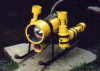
- Motor housing being milled. This motor support system, was easy to build, and allows us to remove a motor in the field.
- IMG_0245 (Large).JPG (54.74 KiB) Viewed 7156 times
-
- In this photo you can see the motor housing being milled. I made the jig in the photo to clamp the 2" PVC pipe coupling while it was being milled. The slots are .25" wide and were milled .600 deep. This allowed the .25" motor supports to be pushed in and then a .35" thick slice from a 2" PVC pipe was installed to hold the motor supports in place.
- IMG_0246 (Large).JPG (61.13 KiB) Viewed 7156 times
-
- Vert thruster tubes have been mounted.
- IMG_0247 (Large).JPG (99.46 KiB) Viewed 7156 times
-
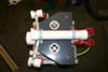
- The rear bulkhead with made with a .25" well in the middle to allow me to pot the female bullet connectors with slow setting epoxy. I cleaned the PVC with PVC pipe cleaner before the connectors were potted. This allowed the epoxy to bond to the PVC.
- IMG_0240 (Large).JPG (88.17 KiB) Viewed 7156 times
-
- We explored several options to get the topside data and power into the ROV, and to save time, space and money, we opted to hard connect the tether directly to the rear bulkhead. If all works and has been fulley tested, we may re-visit this area of the ROV. All of the motor power wires and LED light wires are connected with bullet connectors. This has been a great way to pass wires through the rear bulkhead. The bulkhead has been pressure tested to 115psi (approx 250 water depth)
- IMG_0239 (Large).JPG (81.24 KiB) Viewed 7156 times
-
- Top view of ROV. We used two vert. thrusters with counter rotating props. This gave us good up and down control.
- IMG_0262 (Large).JPG (80.45 KiB) Viewed 7156 times
-
- Wide angle of the front. During our first water test. The ROV was negative buoyant, and we needed to add the 2" upper buoyancy tube. This proved to be a good addition, along with the balast in the two skids.... This allowed us to move the CG (center of gravity) below the main electronics tube, making it very stable. You can place the ROV in any position underwater and it rights it's self.
- IMG_0256 (Large).JPG (74.84 KiB) Viewed 7156 times
-
- Front view of the ROV. Camera has 120 degrees of tilt.
- IMG_0263 (Large).JPG (81.09 KiB) Viewed 7156 times
-
- Rear view of the ROV. We explored several options to get the topside data and power into the ROV, and to save time, space and money, we opted to hard connect the tether directly to the rear bulkhead. If all works and has been fulley tested, we may re-visit this area of the ROV. All of the motor power wires and LED light wires are connected with bullet connectors from Hobby King. This has been a great way to pass wires through the rear bulkhead.
- IMG_0258 (Large).JPG (84.18 KiB) Viewed 7156 times
Re: ROVer
The control system uses the ROV Asia control system. The main electronics board houses the camera and camera tilt. A video balun, 4 ESC (electronic speed controls), and the three control boards.
I used 30 brushless RC car ESC's that I bought from Hobby King. I also bought the programming card, which made it easier to program all 4 ESC, plus the 5th one we have as a spare.
I will cover the Topside drivers control in the next post.
I used 30 brushless RC car ESC's that I bought from Hobby King. I also bought the programming card, which made it easier to program all 4 ESC, plus the 5th one we have as a spare.
I will cover the Topside drivers control in the next post.
- Attachments
-
- programming card.jpg (98.47 KiB) Viewed 7155 times
-
- ESC.jpg (66.42 KiB) Viewed 7155 times
-
- Slide2.JPG (76.86 KiB) Viewed 7155 times
-
- Slide3.JPG (84.89 KiB) Viewed 7155 times
-
- Slide4.JPG (97.67 KiB) Viewed 7155 times
-
- Slide5.JPG (92.88 KiB) Viewed 7155 times
-
- Slide6.JPG (70.96 KiB) Viewed 7155 times
-
- Slide7.JPG (60.88 KiB) Viewed 7155 times
-
- Slide8.JPG (59.79 KiB) Viewed 7155 times
Re: ROVer
The driver control is built into a USB RC airplane simulator. I stripped out the USB cable and wired it up.
The ROV video is displayed on a laptop using a downloadable software package called AMCAP.EXE
The current 100' tether is rolled up on a garden hose reel. This makes it easier to handle and keeps everything clean.
The ROV video is displayed on a laptop using a downloadable software package called AMCAP.EXE
The current 100' tether is rolled up on a garden hose reel. This makes it easier to handle and keeps everything clean.
- Attachments
-
- Slide2.JPG (74.58 KiB) Viewed 7155 times
-
- Slide3.JPG (81.69 KiB) Viewed 7155 times
-
- Slide4.JPG (76.33 KiB) Viewed 7155 times
-
- Slide5.JPG (92.36 KiB) Viewed 7155 times
-
- Slide6.JPG (83.71 KiB) Viewed 7155 times
-
- Slide7.JPG (76.12 KiB) Viewed 7155 times
-
- Slide8.JPG (101.43 KiB) Viewed 7155 times
-
- Slide9.JPG (134.52 KiB) Viewed 7155 times
-
- Slide10.JPG (56.25 KiB) Viewed 7155 times
Re: ROVer
Just back from the lake. Sent ROVer out on his first swimming lesson. Went down to 60 feet three different time. The lake that we were on had poor visibility, but you could see that you were on the bottom, and we tracked its decent on the boats sonar.
After the deeper dives we drove it in the shallower water.
No leaks.... Yaaaa.
Jim and Mike
After the deeper dives we drove it in the shallower water.
No leaks.... Yaaaa.
Jim and Mike
Re: ROVer
Wow.... she looks great and great documentation too, can't wait to see some video.
-Steve
-Steve