Hi KR2_Diving,
After giving it some more thought, I might be able to use the present ROV chassis for the six Thruster configuration without much modification. By lowering the four horizontal Thrusters to the bottom of the chassis and taking out the lower half of the center supports in the side plates along with opening up the rear side plate cutouts to the same outline as the rest of the cutouts. This would give me a very large opening in the lower half of the chassis that would not obstruct the flow of water through the vectored horizontal Thrusters.
Comments?
Regards,
SSN626B/TCIII
Experimental ROV Design using Blue Robotics Components
Re: Experimental ROV Design using Blue Robotics Components
Hi All,
Since I have completed assembling the components outside of the WTCs I have gone ahead and began to fabricate components that will reside inside the WTCs. In this case I started with the Power Junction and Signal Junction Boards that Blue Robotics provides if you purchase the ESCs with the T100 Thrusters.
Since the ESC 16 gauge power cables are Teflon coated they are fairly stiff so I decided to attach individual 16 gauge silicone wires to the + and - output terminals on the Power Junction Board. I made the cable pairs long enough so that I will have some flexibility when splicing the Power Junction cable pairs into the cable penetrator 16 gauge ESC power cables. I also attached a 14 gauge cable pair to the Power Junction Board power input pads which will connect the LiPo batteries to the Power Junction Board. A picture of the completed Power Junction Board is shown below:

Power Junction Board with input and output Power Cables
After completing the Power Junction Board I moved on to the Signal Junction Board. The Signal Junction Board essentially provides a way to conveniently terminate the four wire control cable coming from each ESC and to be able to separate the PWM signal lines from the I2C signal lines. Like the Power Junction Board, I decided to attach pigtail wires, of sufficient length, of the same color and size as the wires in the ESC control cable so that I would have some flexibility when splicing them to the cable penetrator ESC control cable wires. The input end of the Signal Junction Board provides solder pads for the I2C ground, SCL and SDA control signals plus a ground and eight pads for the ESC PWM drive signals. A picture of the Signal Junction Board is shown below:

Signal Junction Board with ESC PWM and I2C wires attached
My next step will be to fabricate two 1/4" thick HDPE Trays, one for each WTC, to mount these two Junction Boards. The Power Junction Board will be mounted on the Battery WTC Tray which will also hold the two 3S 8000mah LiPo batteries, and the Signal Junction Board will be mounted on the Navigation Controller WTC Tray which will also include the navigation controller and other associated components.
More to come.
Regards,
SSN626B/TCIII
Since I have completed assembling the components outside of the WTCs I have gone ahead and began to fabricate components that will reside inside the WTCs. In this case I started with the Power Junction and Signal Junction Boards that Blue Robotics provides if you purchase the ESCs with the T100 Thrusters.
Since the ESC 16 gauge power cables are Teflon coated they are fairly stiff so I decided to attach individual 16 gauge silicone wires to the + and - output terminals on the Power Junction Board. I made the cable pairs long enough so that I will have some flexibility when splicing the Power Junction cable pairs into the cable penetrator 16 gauge ESC power cables. I also attached a 14 gauge cable pair to the Power Junction Board power input pads which will connect the LiPo batteries to the Power Junction Board. A picture of the completed Power Junction Board is shown below:
Power Junction Board with input and output Power Cables
After completing the Power Junction Board I moved on to the Signal Junction Board. The Signal Junction Board essentially provides a way to conveniently terminate the four wire control cable coming from each ESC and to be able to separate the PWM signal lines from the I2C signal lines. Like the Power Junction Board, I decided to attach pigtail wires, of sufficient length, of the same color and size as the wires in the ESC control cable so that I would have some flexibility when splicing them to the cable penetrator ESC control cable wires. The input end of the Signal Junction Board provides solder pads for the I2C ground, SCL and SDA control signals plus a ground and eight pads for the ESC PWM drive signals. A picture of the Signal Junction Board is shown below:
Signal Junction Board with ESC PWM and I2C wires attached
My next step will be to fabricate two 1/4" thick HDPE Trays, one for each WTC, to mount these two Junction Boards. The Power Junction Board will be mounted on the Battery WTC Tray which will also hold the two 3S 8000mah LiPo batteries, and the Signal Junction Board will be mounted on the Navigation Controller WTC Tray which will also include the navigation controller and other associated components.
More to come.
Regards,
SSN626B/TCIII
Re: Experimental ROV Design using Blue Robotics Components
Hi All,
I completed the Battery Compartment WTC battery tray today and am ready to attach the ESC power cables to the Power Junction Board cable leads.
The main battery tray is made up of a sub tray on which the batteries will be mounted and a platform in the rear of the battery tray to mount the Power Junction Board.
The main battery tray is a 10" long and 3" wide plate made of 1/4" HDPE with beveled edges to match the inner circumference angle of the Battery Compartment WTC. At the rear is a 3" square 1/8" thick plate of ABS plastic that is raised 2 1/4" off of the surface of the main battery tray. The purpose of this platform is to provide a mounting surface for the Power Junction Board. The height of the platform will allow two 5000 mah 3S LiPos on their sides to be slid underneath the platform.
On the front of the main battery tray is the battery sub tray that is held in place by two 4-40 ss machine screws in the front of the main battery tray and in the rear by the two front 2 1/4" spaces that support the Power Junction Board platform. The purpose of the battery sub tray is to allow the removal of the batteries without having to remove the main battery tray. Slots will be cut into the battery sub tray to allow Velcro Straps to be wrapped around the two 3S LiPo batteries that will be stacked vertically on their sides.
The individual ESC power leads coming from the Power Junction Board will be connected to the ESC power cables in the back of the rear End Cap using 3.5 mm bullet banana plug connectors which will allow for easy removal of the End Cap should the need arise.
The following pictures below will give an idea of how the Main Battery tray is constructed and its placement in the Battery Compartment WTC:

Main Battery Tray and Battery Sub Tray

Battery Sub Tray in place on Main Battery Tray

Top view of Power Junction Board mounted on top of Main Battery Tray

Front View of Main Battery Tray in WTC

Side View of Power Junction Board in WTC

Top View of Power Junction Board in WTC
Tomorrow I will be begin attaching the male and female 3.5 mm bullet banana plugs to the Power Junction Board power cables and the ESC power cables in the cable penetrators in the rear of the rear Battery Compartment WTC End Cap.
More to come.
Regards,
SSN626B/TCIII
I completed the Battery Compartment WTC battery tray today and am ready to attach the ESC power cables to the Power Junction Board cable leads.
The main battery tray is made up of a sub tray on which the batteries will be mounted and a platform in the rear of the battery tray to mount the Power Junction Board.
The main battery tray is a 10" long and 3" wide plate made of 1/4" HDPE with beveled edges to match the inner circumference angle of the Battery Compartment WTC. At the rear is a 3" square 1/8" thick plate of ABS plastic that is raised 2 1/4" off of the surface of the main battery tray. The purpose of this platform is to provide a mounting surface for the Power Junction Board. The height of the platform will allow two 5000 mah 3S LiPos on their sides to be slid underneath the platform.
On the front of the main battery tray is the battery sub tray that is held in place by two 4-40 ss machine screws in the front of the main battery tray and in the rear by the two front 2 1/4" spaces that support the Power Junction Board platform. The purpose of the battery sub tray is to allow the removal of the batteries without having to remove the main battery tray. Slots will be cut into the battery sub tray to allow Velcro Straps to be wrapped around the two 3S LiPo batteries that will be stacked vertically on their sides.
The individual ESC power leads coming from the Power Junction Board will be connected to the ESC power cables in the back of the rear End Cap using 3.5 mm bullet banana plug connectors which will allow for easy removal of the End Cap should the need arise.
The following pictures below will give an idea of how the Main Battery tray is constructed and its placement in the Battery Compartment WTC:
Main Battery Tray and Battery Sub Tray
Battery Sub Tray in place on Main Battery Tray
Top view of Power Junction Board mounted on top of Main Battery Tray
Front View of Main Battery Tray in WTC
Side View of Power Junction Board in WTC
Top View of Power Junction Board in WTC
Tomorrow I will be begin attaching the male and female 3.5 mm bullet banana plugs to the Power Junction Board power cables and the ESC power cables in the cable penetrators in the rear of the rear Battery Compartment WTC End Cap.
More to come.
Regards,
SSN626B/TCIII
Re: Experimental ROV Design using Blue Robotics Components
Hi All,
I spent Saturday soldering the 3.5 mm male banana plugs onto the 16 gauge silicone power wires attached to the Power Junction Board and covered each male plug with shrink sleeving.
On Sunday I cut the ESC 16 gauge power cable wires in the cable penetrators to 3/4" long, stripped the insulation from the wires, soldered on the 3.5 mm female banal connectors and then covered the connectors with shrink sleeving.
With the two female connectors side by side they just fit though the cable penetrator hole in the 10 hole End Cap. Attempting to pass the two female connectors though the cable penetrator clamping nut looked like they wouldn't make it until I first put one though the nut hole and then flexed the wire on the other connector to the point that it could get it through the nut hole directly behind the first connector. Lucky me
Tomorrow I plan to make an adapter with one of my spare blank cable penetrators to be able to attach a vacuum pump to the battery compartment WTC. I plan to just have the End Caps in place because the battery tray will probably outgas like crazy (I used to test satellite payloads in vacuum chambers so I know all about outgassing:-)) and it will take more time that I care to spend to achieve a steady vacuum reading. Without the battery tray in place I should be able to reach a steady vacuum reading in a reasonable period of time. Then I can find out what the leak rate is and see if it is reasonable.
More to come.
Regards,
SSN626B/TCIII
Re: Experimental ROV Design using Blue Robotics Components
Hi All,
Today was fairly productive for me as I fabricated the WTC vacuum pump adapter fitting and cut out the navigation controller tray for the navigation controller WTC.
To fabricate the WTC vacuum pump adapter I started with a blank cable penetrator and machined one through hole and two counter bores into the body of the penetrator that mimicked the standard Blue Robotics 6 mm cable penetrator. I drilled the through hole and the two counter bores with my cheapie Skill drill press to see how well the holes would align and they came out pretty concentric:

Blank Cable Penetrator machined to accept Vacuum Tubing Plastic Splice
The machining of the blank cable penetrator was then followed by CAing one of the Vacuum Pump plastic tubing plastic splice into the lowest counter bore. I then mixed up some Loctite Marine grade epoxy and filled in the area of the upper counter bore between the body of the cable penetrator and the plastic tubing splice:

Plastic tubing splice potted into machined Cable Penetrator
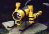
The following two pictures show the Harbor Freight Vacuum Pump and the complete WTC Vacuum Testing Components:

Hand Vacuum Pump

WTC Vacuum Testing Components
While I was waiting for the epoxy to cure I cut a piece of 1/4" thick HDPE to the same dimensions (3" x 10") as the battery compartment tray to fabricate the navigation controller compartment tray. Like I did with the battery compartment tray, I beveled the edges of the tray so that the edges of the tray are tangent to the inner circumference of the navigation controller WTC.
Tomorrow I will proceed to finish the fabrication of the navigation controller compartment tray and attach the Signal Junction Board to the tray.
More to come.
Regards,
SSN626B/TCIII
Today was fairly productive for me as I fabricated the WTC vacuum pump adapter fitting and cut out the navigation controller tray for the navigation controller WTC.
To fabricate the WTC vacuum pump adapter I started with a blank cable penetrator and machined one through hole and two counter bores into the body of the penetrator that mimicked the standard Blue Robotics 6 mm cable penetrator. I drilled the through hole and the two counter bores with my cheapie Skill drill press to see how well the holes would align and they came out pretty concentric:
Blank Cable Penetrator machined to accept Vacuum Tubing Plastic Splice
The machining of the blank cable penetrator was then followed by CAing one of the Vacuum Pump plastic tubing plastic splice into the lowest counter bore. I then mixed up some Loctite Marine grade epoxy and filled in the area of the upper counter bore between the body of the cable penetrator and the plastic tubing splice:
Plastic tubing splice potted into machined Cable Penetrator
The following two pictures show the Harbor Freight Vacuum Pump and the complete WTC Vacuum Testing Components:
Hand Vacuum Pump
WTC Vacuum Testing Components
While I was waiting for the epoxy to cure I cut a piece of 1/4" thick HDPE to the same dimensions (3" x 10") as the battery compartment tray to fabricate the navigation controller compartment tray. Like I did with the battery compartment tray, I beveled the edges of the tray so that the edges of the tray are tangent to the inner circumference of the navigation controller WTC.
Tomorrow I will proceed to finish the fabrication of the navigation controller compartment tray and attach the Signal Junction Board to the tray.
More to come.
Regards,
SSN626B/TCIII
-
KR2_Diving

- Posts: 391
- Joined: Aug 30th, 2012, 11:43 am
- Location: Currently: NW Suburbs of Chicago. Originally: NE Wisconsin
Re: Experimental ROV Design using Blue Robotics Components
Really enjoying this thread! I am learning A LOT! Keep it up!
Would like to ask about the vacuum element of this... I understand the basic concept that the batteries may off gas as they discharge as part of the chemical reaction that actually creates the power that the batteries are used for... but somehow I am missing a few pieces to the puzzle... what are you up to with the Vacuum pump and WTC fitting? IS this just for a test... or for actual use in dives?
What am I missing here?
Thanks,
Ryan
"KR2_Diving"
Re: Experimental ROV Design using Blue Robotics Components
Hi KR2_Diving,
Since I want to determine the possible leak rate (effectiveness) of the End Cap double O ring seals, the cable penetrator O ring seals, and the effectiveness of the cable potting without putting the WTC into the water and letting it sink to 100 ft and sit a while before bringing it to the surface, pulling a vacuum on the inside of the WTC with the End Caps in place is the next best thing.
By pulling a high vacuum in the WTC I can simulate the pressure of the water pressing against the End Cap double O ring seals, the cable penetrator O ring seals and the cable potting to help me determine if the O rings are providing a good seal and that there are no leaks through the cable penetrator potting.
The reason that I am using an empty WTC for the test is to avoid the outgassing of the tray materials and batteries that will occur when I draw a vacuum on the WTC. The only items that will outgas will be the ends of the ESC power cable wires/connectors that protrude into the WTC interior which, when completely outgassed, will no longer contribute to the vacuum within the WTC. A this time the only contribution to the vacuum within the WTC will be any leaks around the various WTC seals and the cable penetrator epoxy potting.
Regards,
SSN626B/TCIII
Re: Experimental ROV Design using Blue Robotics Components
I love how neat those junction boxes make everything, this thing is turning out awesome.
-Steve
-Steve
Re: Experimental ROV Design using Blue Robotics Components
Hi All,
Trying to use the Harbor Freight hand powered vacuum pump turned out to be less than satisfactory as it failed after about eight hours of use.
The acorn nut that is used to anchor the vacuum pump piston to the moving part of the pump handle stripped out and shot across the shop floor while I was pumping down the battery compartment WTC. I tried to reattach the acorn nut to the piston shaft, but that is when I determined that the threads were stripped and it came apart again on the first pump of the handle.
So I got on Amazon to see what I could purchase in the way of an electrical powered vacuum pump. Amazon has a fair assortment of oil vane vacuum pumps starting at around $60 on up depending on pumping capacity. These type of oil vane pumps can reach vacuums in the low millibar region which is way beyond what is required for simple vacuum testing purposes.
Amazon also sells a 12 vdc oil less vacuum pump that received a very high rating. Most users indicated that it could pull between an 18 - 22 in vacuum without getting hot which is more than adequate for my vacuum testing requirements. So I ordered one and it will be here this Sunday.
In the meantime I will have to get a vacuum gauge to go with my vacuum test setup. I have removed the vacuum gauge from the HF defunct vacuum pump, but I think the threads are metric as the threaded stub is 10 mm in diameter. However I might be able to find a 10 mm diameter to 1/4" barbed tubing adapter at Home Depot. The fall back position will be to go to Harbor Freight (ya, those guys again) and spend $15 for an automotive vacuum gauge so I can proceed with the WTC vacuum testing.
Before the HF vacuum pump failed I was troubleshooting a 20 mm Hg/ minute leak in the battery compartment WTC which has been hard to find. I was in the process of replacing each ESC power cable penetrator with a blank cable penetrator, but had yet to pump down with the blank penetrator in place of the ESC power cable penetrator.
I conversed with Rusty at BR about the leak and he told me that they had not leak tested the ESC power and signal cables, but would do so in light of my leak rate issue.
More to come.
Regards,
Re: Experimental ROV Design using Blue Robotics Components
Yeah it could be the wires I know water can leak in through the jackets so I use to strip off some of the jacket off when potting but even then from tests Bubbles has done (Read Here) it can still leak in through stranded potted wires. He's done some more work with penetrators that might give you some ideas. I've tried to use a solid pass through too (Seen Here) but haven't really tested them at pressure yet.
Anyway those might give you some ideas if the wires turn out to be the problem.
-Steve
Anyway those might give you some ideas if the wires turn out to be the problem.
-Steve