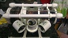
Here's what my power control board looks like fully assembled:
I've put all the high power circuitry (14.8 V and about 6 A for each thruster at full power) on a separate PCB because the MAX7456 video overlay is rather sensitive to electrical noise and since I control the motors using 20 kHz PWM, there's a fair bit of noise.
That is so nice Jens. Wish i had your brain in some way
Can i buy a DIY soldering kit from you of that
My own progress now is, i bought a 3D printer my self to help me get more done without using metal. My design is almost as i want it. Quite alot changed since i got the job as a ROV Pilot offshore. Talked to more out here that is working on their own.
@jonny: speed only. I run the motors in one direction only. And the board doesn't even generate the PWM signal for speed control – it just amplifies the signal from the microprocessor (which is just 3.3 V and 4 mA) so I can control high voltage, high current motors from the MCU.
And it also isolates the motor circuits from the MCU so the MCU and other digital components are not disturbed by electrical noise from the motors.
OK, I need to ask a question and this may be where I get a good answer. I am using an UNO for control in my ROV. I have some ESC's, but I am having a little trouble with them. Also I am using brushed motors. I really like the idea of using FET's. It seems I can do whatever with the UNO and since it has a PWM output I just need the FET for the current. I am going between forward and reverse with a relay for now. My question is what are the pro's and con's of driving a FET with the PWM output from the UNO vs an ESC?
CLYON wrote:OK, I need to ask a question and this may be where I get a good answer. I am using an UNO for control in my ROV. I have some ESC's, but I am having a little trouble with them. Also I am using brushed motors. I really like the idea of using FET's. It seems I can do whatever with the UNO and since it has a PWM output I just need the FET for the current. I am going between forward and reverse with a relay for now. My question is what are the pro's and con's of driving a FET with the PWM output from the UNO vs an ESC?
Chuck
Honestly an ESC should work well with the arduino as it provides 6 PWM ports, If you are having trouble with them just post a description on the Arduino forums and they should be able to help you. Another good forum to look at about interfacing Arduino to ESC would be any quadrotor forum.
Hope I could help, Jack
I went ahead and built a board with MOSFET's and relays for reverse and used the PWM's from the UNO. There were two problems I had with the ESC's that I had. The first was a delay when you first applied power, because it had to check for a signal. The second was that when you applied full power it started cutting the power back. The data sheet said it was low voltage cutoff, but the battery had never gone down. It also always beeped when there was a good signal, I didn't know if this was normal, but it drove me crazy. I will monitor voltage with the UNO.