|
Mayfair 750 GPH Bilge Pump Thruster Testing
|
|
|
 |
|
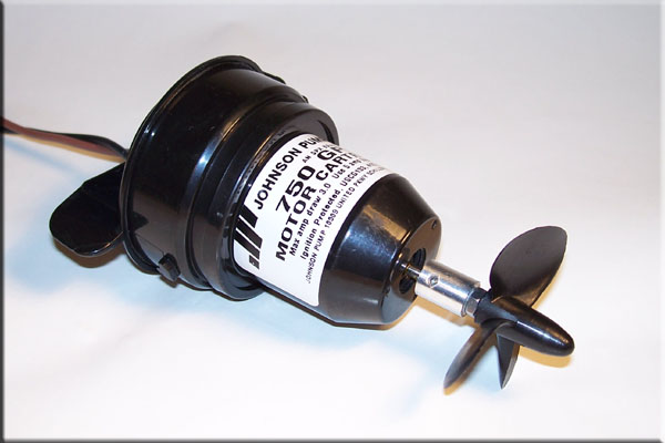
This is a 750 GPH Mayfair Bilge Pump Replacement Motor Cartridge made by Johnson Pump. These are popular for use as Rov Thrusters among the home built crowd because they are easy to convert and cost under $20. I bought one of these to finally answer the age old question of....."How deep can a bilge pump go before it leaks?" Before I sacrifice this one to answer that question I thought I would test out a few props first to see what kind of performance one can expect from one of these.
|
|
|
 |
|
These first two props are a 50mm and a 60mm, these are both 3 blade plastic boat propellers made by Robbe, these were bought from Harbor Models. I will be testing Amp Draw as well as Pounds of Thrust put out by each prop.
|
|
|
 |
|
Here you can see the difference in size as well as shape between the two props.
|
|
|
 |
|
The first test was with the 50mm 42 pitch prop. It put out about 1.8 Lbs. (1 lb. 12.8 ozs.) of forward thrust while drawing around 6.0 Amps. In reverse it put out 1.4 Lbs. (1 lb. 6.4 ozs.) while drawing 5.5 Amps. Peak thrust was about 2 Lbs. but it tappers off to 1.8 after a few seconds.
|
|
|
 |
| The 60mm 45 pitch prop only put out 1.5 Lbs. (1 lb. 8 ozs.) of forward thrust while drawing 6-7 amps. Reverse was only .8 Lbs. (12.8 ozs.) while drawing 6.30 Amps. I think the added pitch and prop surface area of the 60mm is a little to much for this motor. |
|
|
 |
 |
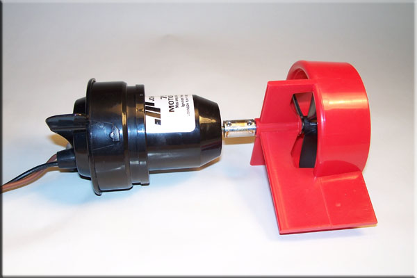
| I also bought this Kort Nozzle with special prop made by Robbe to see if a Kort nozzle would improve performance. It turns out the special prop is the same 60mm prop I bought. I had to turn a new prop adapter to test this out as is did not come with a shaft. The nozzle actually has a airplane wing shape to it but it didn't seem to make any difference, it still put out around 1.5 Lbs. of thrust. At $20 though I think a simple PVC shroud would be a better idea. |
|
|
 |
| From this chart you can see the 50mm prop put out the most thrust when it comes to the Robbe 3 Blades. This is the same prop I used on my converted Rule 1100 Pumps. I get about 2.3 Lbs. using that pump but they cost a lot more and require removal of the impeller housing. |
|
|
 |
|
The next batch of props I tested were all bought from Hobby Lobby. I don't know the exact pitch of any of the props from Hobby Lobby but these (from Left to Right) are 35,40,45, and 50mm in size and are labeled "X-BRAND" high pitch nylon props made for electric Race Boats. They put out from 1.3 to 1.7 Lbs. of thrust at 4.2 to 6 Amps respectively. (see the chart at the bottom)
|
|
|
 |
|
This picture shows the general pitch of the props. The only thing I noticed about all the 2 blade props I tested were the thrust and amps were constantly varying, the reading never stayed constant.
|
|
|
 |
|
This next batch of props are all made by Graupner. (from Left to Right) they are 35,45,40,50, and 50mm) I wanted to try a few of the 60mm props they have but they weren't available at the time I bought them. (again see the chart below to see the results.)
|
|
|
 |
|
This picture also shows the different pitches of the props.
|
|
|
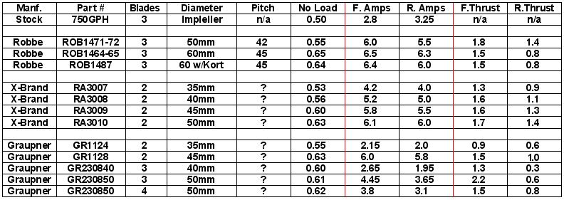 |
| This chart shows all of the props I have tested so far. Both of the 50mm Three Blade props preformed the best. The Graupner prop put out more forward thrust with less amp draw over the Robbe prop but the Graupner prop had a significant loss of thrust in reverse as you can see from the chart. (Actually all of the Graupner Props have a significant loss in reverse.) This might be ok for horizontal thrusters because you may not use reverse as much as forward but for the vertical thruster this would be a huge problem because you have to go up just as much as you go down. |
|
|
 |
|
Here are the top two performers Robbe on the left, Graupner on the right. They are both 3 blade 50mm props but have totally different blade size and shape.....
|
|
|
 |
|
....they also both have different pitches. The Robbe prop on the left has a 42 degree pitch and I'm not sure what the Graupner prop is, they do not list the pitch of any of their 3 or 4 blade props.
|
|
|
|
On to the Pressure Testing.
|
|
|
 |
|
I don't want to play any guessing games so to test out the pump right I need to be able to see exactly when (or at what pressure) the seals leak so I can't just put the pump in the pressure chamber and guess when that was. I also need to be able to run the pump to see if the spinning shaft has any effect on the shaft seal. The way I am going to do this is to only have the wet half of the seals inside the housing and the dry half where I can see them. Using a hobby saw I begin by cutting off the top of the pump and removing the rubber seal for the wire exits.
|
|
|
 |
|
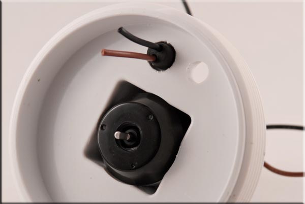
I know everyone is curious so this is the motor that is in the pump, but the only markings on the motor are what are show here.
|
|
|
 |
|
With the entire pump housing being sealed the shaft seal seen here and................
|
|
|
 |
|
......the rubber seal for the wire exits are the only points of failure that are possible so these are what I will be testing.
|
|
|
 |
|
I bought a new plug for my pressure housing and bored a few holes through it, this is how I am going to be able to see what is going on and when. The larger hole is obviously for the pump housing and the 2 smaller holes are for the rubber wire seal and for the pressure release valve. (not show)
|
|
|
 |
|
Here you can see the pump and rubber seal inserted into the plug. It's hard to tell from the picture but I tried to simulate the pump housing best I could so the hole for the rubber wire seal was cut just like the hole on the actual pump housing.
|
|
|
 |
| This picture shows the dry side of the seals and how I will be able to see if or when they leak as I pressurize the housing. |
|
|
 |
| This is the completed plug with the pressure relieve valve installed and the entire test assembly plug screwed onto my pressure chamber ready to be tested. |
|
|
|
I have completed the first pressure test.......
I began the pressure test by slowly increasing the water pressure while watching for any signs of leaks, I was able to reach my maximum water pressure of 95 psi (which simulates a depth of around 200') without either of the seals showing any signs of leaks. The only leak a had was from the actual wires, and this was through the jacket of the wires and not the rubber exit seal. I could however get the rubber wire exit seal to leak a little (and by little I mean a small trickle) if I pulled the wires sharply to the side, which would be expected because I was creating a void in the seal. Keep in mind that this was the back side (dry end) of the seal though and that shouldn't happen on wet side of the seal because that side does have some flexibility to it. After these tests I personally wouldn't even worry about it ever leaking from the rubber exit seal under normal conditions but you could always put some sealant on it for some added protection and piece of mind if you wanted too. I let everything sit under pressure for about 10 minutes and then I proceeded to hooked up the pump to the battery. Everything looked good, still no leaks (besides the trickle from the wires) and the pump was drawing about .8 amps under pressure. (the tests were done with a bare shaft, no prop was used) At this point I varied the pressure to the chamber to see if there would be any change in the amps from the pressure of the seal on the shaft, there wasn't any drastic changes at this point. After letting the motor run for a few minutes I shut it off and left the housing pressurized while I when in to eat and warm up (did I mention it's winter and I'm doing all this while standing in a half foot of snow, I hope you guys appreciate this :) I came back and hour later and still no leaks. I decided to run the motor again, this time for a longer period. I hooked everything back up and the motor was still running at about .8 amps, but after about 20-30 seconds I heard the wine of the motor change and the amps jumped up to 1.5, another few seconds later and they topped out a 3.75 amps, that's not so good considering this is just a bare shaft. I once again varied the pressure and this time it did have an effect on the amps. At this point I decided to open up the housing to see if there was anything noticeable going on with the seal. The seal didn't look any different so I pulled the motor out and powered it back up, with the motor out of the pump housing it only drew .40 amps. I reinserted it back in the housing and powered it up once again and it now draws a little over 1 amp. I only ran the motor for a few seconds to get a reading but I noticed a little smoke coming off the shaft, upon touching the shaft I burn my finger as it was pretty hot. Even after a few hours too let everything cool down, running the motor for even 5 seconds (out of the water) heats the shaft back up to where you can't touch it. It also now draws 3 amps at start up and then settles down to 1.25, if I run the shaft end in the water it peaks at over 2 amps with no load. The pressure definitely affected the seal to where it might be ruined, I'll have to run a few more test but I think I might have to start with a fresh pump at this point. In hindsight I probably should have only started out at say 50' of simulated depth and did all the various test and then worked up from there to get a max workable depth. I think the pressure was just to high for this seal and maybe the added drag on the shaft caused it to heat up too much and that probably deformed the seal? I just don't know for sure because it didn't happen the first time I ran. Overall even though I didn't actually answer the question "How deep can they go?" I don't think the test was a total failure, after all the seals never did actually leak but I think if I tried to run a propeller on one with the added drag of the seal at that pressure it would probably cause too much of a draw on the motor. For the price of the pumps though I think I would be comfortable running them at half of what I tested say 100'. This is just a guess at this point so use this info at your own Risk. I may do some more testing in the future but as of right now my budget for testing is about dried up. Update - 1-10-09 It turns out the seal may not have been deformed after all, I pulled the motor back out of the pump housing and regreased the shaft and the motor is now drawing around .67 amps. While the seal never leaked I'm now speculating that the pressure was enough to push what ever grease is around the shaft back into the housing away from the seal and this may have caused the excess drag and heating problem. I'm not sure how to over come this problem besides not diving so deep because I don't think its as simple as just regreasing the shaft now and then, as I don't think it can be done from the out side. I still need to continue the testing to figure out an acceptable depth at which the pumps are safe to use at. |
|
|
 |
|
I decided to test out the Robbe 35 and 40mm 3 blade props just to see how they compare to the 50mm they are pictured with here.
|
|
|
 |
 |
| I also made a simple shroud out of 1 1/2" PVC pipe which both the 35 and 40mm props will fit into. (shown here with the 40mm) This was just quick test and all the edges were left square, I little shaping or experimenting with length might help the flow a bit. |
|
|
 |
| You can see from the chart above that the shroud did cut down the thrust a little but the amps dropped also. The 40mm put out only a little over a 1/4 lb. of thrust less then the 50mm but at a full amp less so this is something to think about when selecting a prop. |
|
|
|
If you have any other questions I didn't cover feel free to E-mail me.
|
|
|
 |
| All Information, Pictures, and Material is copyright © 1998-2009 by Stephen Thone and may not be used for any personal or commercial purposes without the consent of the author. All rights reserved. The Author makes no guarantees or warranties as to the accuracy or completeness of, or results to be obtained from accessing and using the Information herein. | |||