|
How To's
Relay Wiring for "H" Bridge Relays |
|
|
|
This section shows wiring for a control system using EP2R-B3G1 6V "H" Bridge Relays. These can be found at The Electronics Goldmine (Item# G14951) These are cheap at under a $1.00 and this setup only requires 1 Relays for every Thruster used which saves space in the control box. These only have a 6 volt coil but I've been using 12 volts and haven't had any problems yet. This system as shown will allow for basic on/off control of 3 thrusters and one light but more could be added easily. (Apparently these relays are no longer available from The Electronics Goldmine but I will leave this How To up anyway just incase they ever get more.)
|
|
|
 |
|
This is what the bottom of the "H" Bridge Relay and bottom of a Standard DPDT Relay consists of.
|
|
|
 |
|
You will need 3 "H" Bridges for the Thrusters and 1 DPDT Relay for the Lighting. I usually line them up and glue/tape them together to make it easier to solder all of the connections.
|
|
|
 |
|
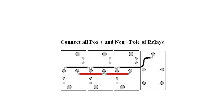
Start by soldering on wires to connect all of the Pos. and Neg. Poles as shown.
|
|
|
 |
|
Then you will connect one side of each coil to the next.
|
|
|
 |
|
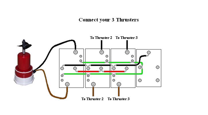
The next step will be connecting your actual Thrusters. Normally the Relays will be sealed in a box (not shown) and the thruster wires will have to be feed into that box before soldering them on. (as well as the rest of the wires in the next steps) You can see how I did this on my Retrofit Seafox Control Box Page.
|
|
|
 |
|
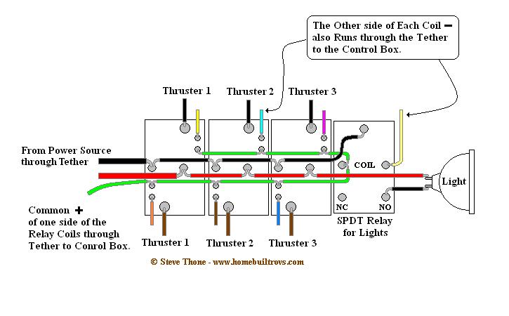
Next you will connect the wiring for your lighting. The Positive comes from the last relay and the negative wire will connect to the NC pole of the SPST Relay as shown.
|
|
|
 |
|
The Main Power Wires from your Tether are connected next. The main power wires are shown here tied into the first relay but they can be connected to any of the relays if it's easier. I use 16 Gauge speaker wire for main power because it's cheap and readily available. But the gauge used would depend on the length of your Tether because of voltage drop.
|
|
|
 |
|
Then you will connect the common Positive for the relay coils.
|
|
|
 |
| This is an alternative method for wiring the common positive feed to the relays coils - If your relays coils can handle the same voltage (usually 12 volts) as your thrusters you can tie in the common positive feed (green wire) into the positive power feed connection. (as shown by the red arrows) This with allow one less wire running through the tether too. |
|
|
 |
|
The last wires to connect are your control wires from your tether. These can be anything from cat5 wires to phone wires, I use the latter, again because they are cheap and available anywhere.
|
|
|
 |
|
This is an overview of what the entire setup should look like.
|
|
|
 |
|
|
|
If you have any other questions feel free to E-mail me, or if you actually use this setup let me know how it worked out for you.
|
 |
| All Information, Pictures, and Material is copyright © 1998-2009 by Stephen Thone and may not be used for any personal or commercial purposes without the consent of the author. All rights reserved. The Author makes no guarantees or warranties as to the accuracy or completeness of, or results to be obtained from accessing and using the Information herein. | |||