|
How To's
Relay Wiring for Duel Post Duel Throw Relays |
||
|
|
||
|
This section shows wiring for a control system using common DPDT Relays. (as see in my Control Options How To) this setup requires 2 Relays for every Thruster used. This system as shown will allow for basic on/off control of 3 thrusters but more could be easily added.
|
||
|
|
||
 |
||
|
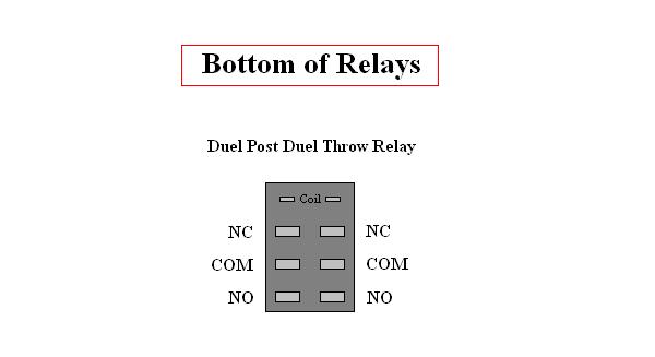
This is what the bottom of a Standard DPDT Relay consists of , there are 8 separate poles. The 2 at the top are for the Coil, the other six will handle the flow. Not all Relays are the same so for this hook up you have to make sure the poles are the same as shown here. The Common Poles are in the Middle, NC (Normal Closed) are at the top (closest to the coil poles) and NO (Normally Open) are at the bottom.
|
||
|
|
||
 |
||
|
Each Thruster will require 2 relays, one controls forward and the other reverse. I usually line them up and glue/tape them together to make it easier to soldering all of the connections.
|
||
|
|
||
 |
||
| Start by soldering on 2 wires to form the cross over. The wires are connected to the NO poles of the top relay to the NC poles of the bottom relay. The cross over works the same as on the Simple Forward/Reverse Switch. | ||
|
|
||
 |
||
|
Next you will solder on two more wires as shown here. You will be connecting the NC poles form the top relay to the NO poles of the bottom Relay. These will be the bypass of the cross over.
|
||
|
|
||
 |
||
|
Next repeat the first few steps to make one duel relay setup for each thruster used.
|
||
|
|
||
 |
||
|
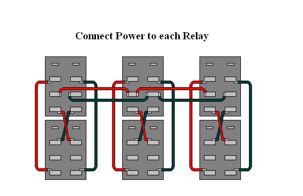
Next you need to link power to all three relay setups, so you will be connecting the Common poles of the top relays only.
|
||
|
|
||
 |
||
|
Then you will connect one side of each coil to the next.
|
||
|
|
||
 |
||
| The next step will be connecting your actual Thrusters. These are connected to the Common poles of the bottom relays. Normally the Relays will be sealed in a waterproof box (not shown) and the thruster wires will have to be feed into that box before soldering them on. You can see how I did this on my Retrofit Seafox Control Box Page. | ||
|
|
||
 |
||
|
The Main Power Wires from your Tether are connected next, these are connect to just one of the Common Poles of a top relay. (again they have to be feed into the box.) I use 16 Gauge speaker wire for main power because it's cheap and readily available. But the gauge used would depend on the length of your Tether because of voltage drop.
|
||
|
|
||
 |
||
|
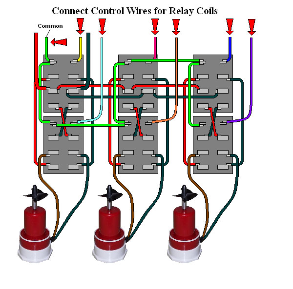
The last wires to connect are your control wires from your tether. These can be anything from cat5 wires to phone wires, I use the latter, again because they are cheap and available anywhere. (see below for an alternative method for wiring the common positive feed (green wire) for the relays coil)
|
||
|
|
||
 |
||
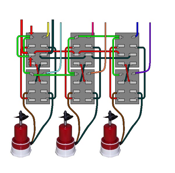
| This is an alternative method for wiring the common positive feed to the relays coils - If your relays coils can handle the same voltage (usually 12 volts) as your thrusters you can tie in the common positive feed (green wire) into the positive power feed connection. (as shown by the red arrows) This with allow one less wire running through the tether too. | ||
|
|
||
 |
||
You can add a light with a simple SPDT Relay, simply connect a Positive and Negative wire from the other relays and tie in the common pos. of the coils as shown. The only draw back to this setup is you have a common draw on power so when your light is on and you turn on a thruster you light will dim.
|
||
|
|
||
|
If you have any other questions feel free to E-mail me, or if you actually use this setup let me know how it worked out for you.
|
||
 |
| All Information, Pictures, and Material is copyright © 1998-2009 by Stephen Thone and may not be used for any personal or commercial purposes without the consent of the author. All rights reserved. The Author makes no guarantees or warranties as to the accuracy or completeness of, or results to be obtained from accessing and using the Information herein. | |||